The following set of parts are all 3D printed. You can download the STL files for these parts here.
 |
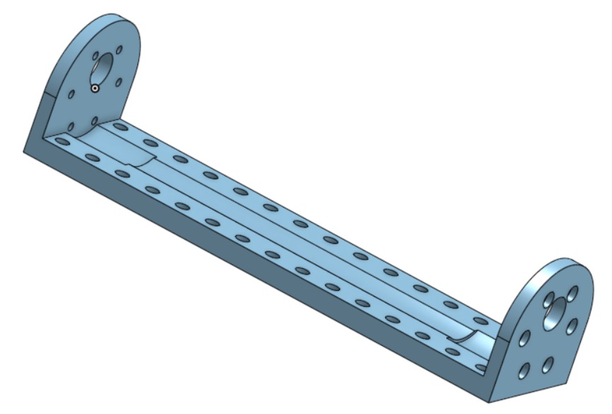
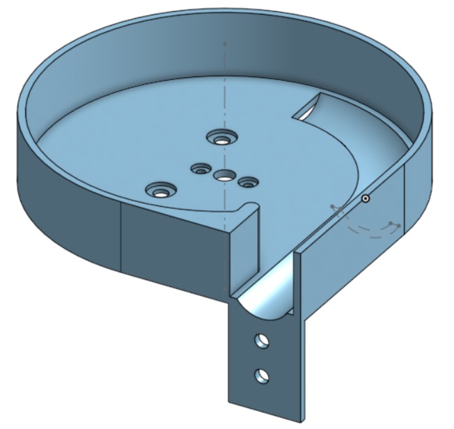
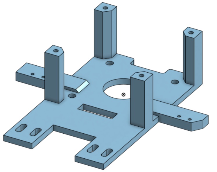
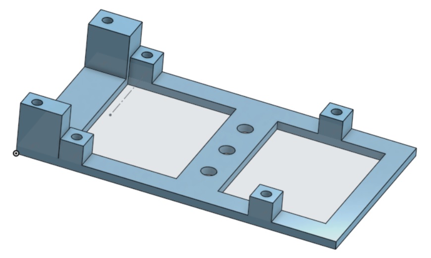
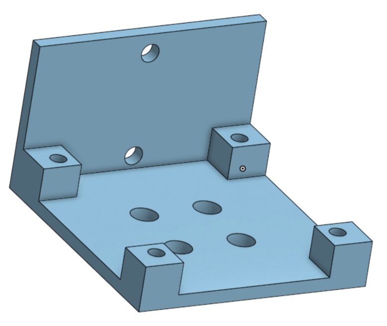
Main Chassis (ChassisLarge.stl) |
 |
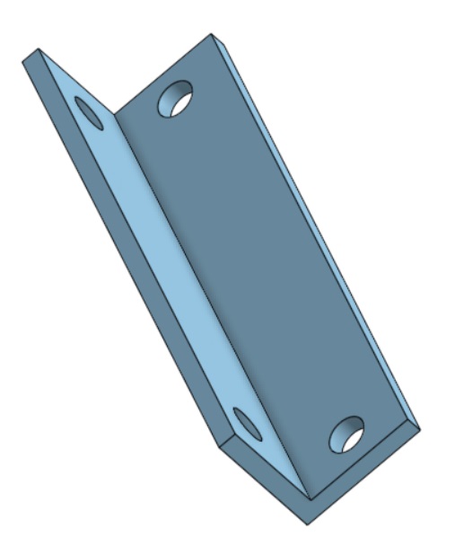
Drive Motor Mount for the short drive motor (DriveMotorMountShort.stl). There is also a separate drive motor mount that would be used for the long drive motors (DriveMotorMountLong.stl). The two motor choices are described below. |
 |
Nerf Ball Feeder (Feeder.stl) |
 |
Feeder Support (FeederSupport.stl). You will need 2 of these. |
 |
Nerf Ball Feeder Rotor (Rotor.stl) |
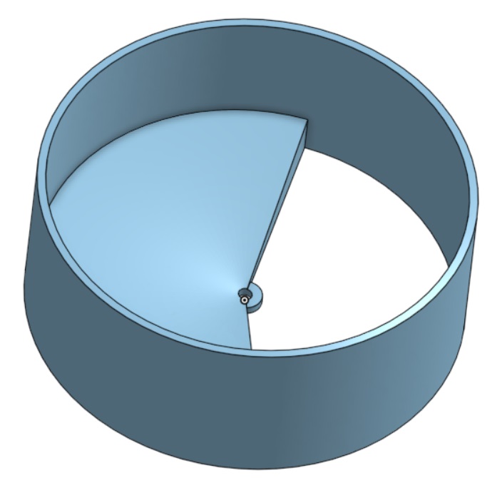 |
Nerf Ball Hopper (Hopper.stl) |
 |
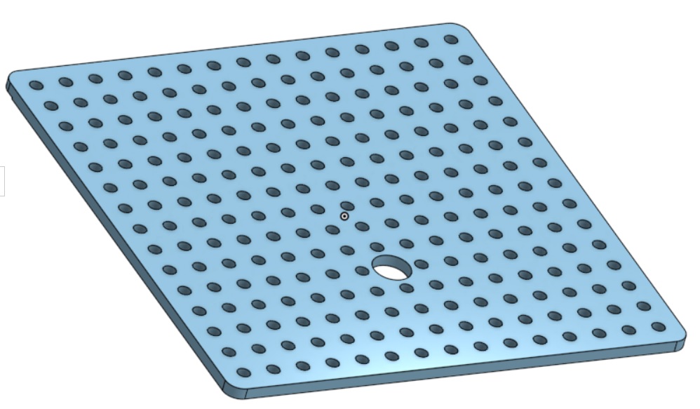
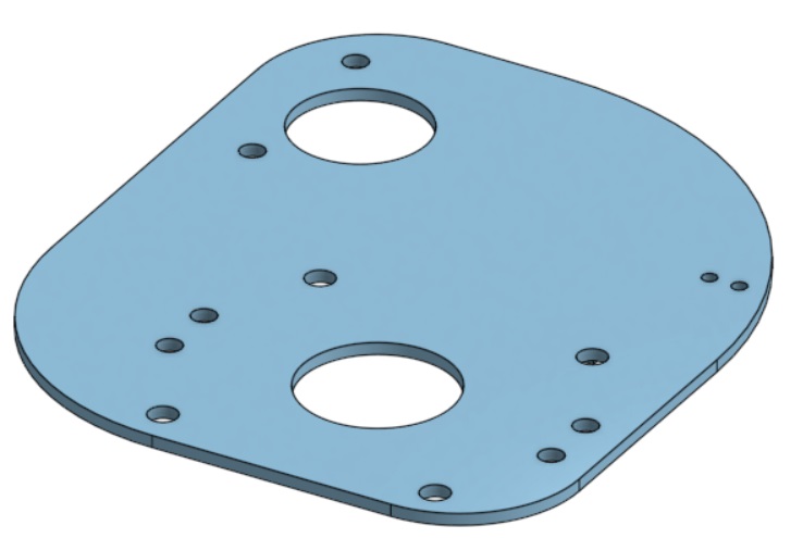
Turntable Bottom Plate (TurntableBottomPlate.stl). |
 |
Turntable Top Plate (TurntableTopPlate.stl) |
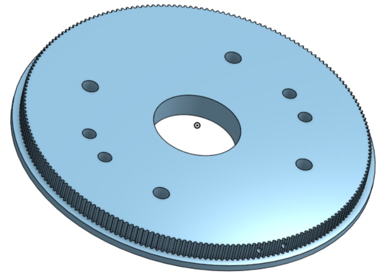 |
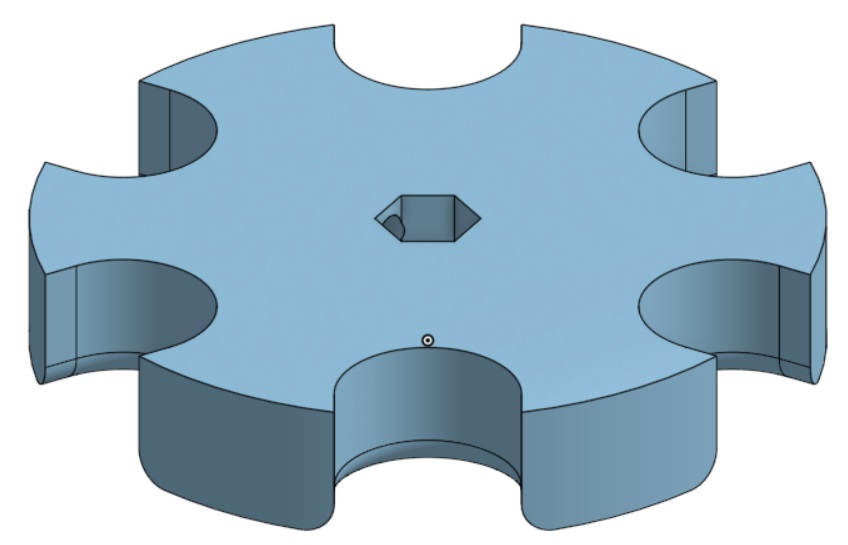
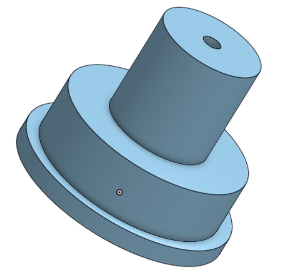
Turntable Gear. The turntable belt attaches to this gear (TurntableGear.stl) |
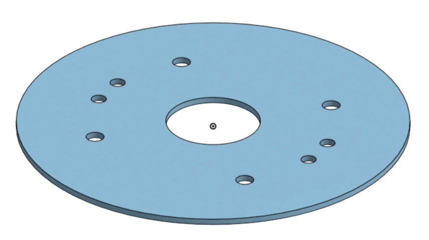 |
Turntable Plate attaches to the top of the turntable gear (TurntablePlate.stl) |
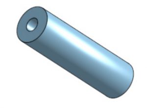
| The Turntable Spacer provides spacing between the Turntable Gear and the Limit Switches (TurntableSpacer.stl). You will need four of these. | |
| The Limit Switch Spacer provides spacing between the Limit Switch and the Turntable Bottom Plate (LimitSwitchSpacer.stl). You will need four of these. | |
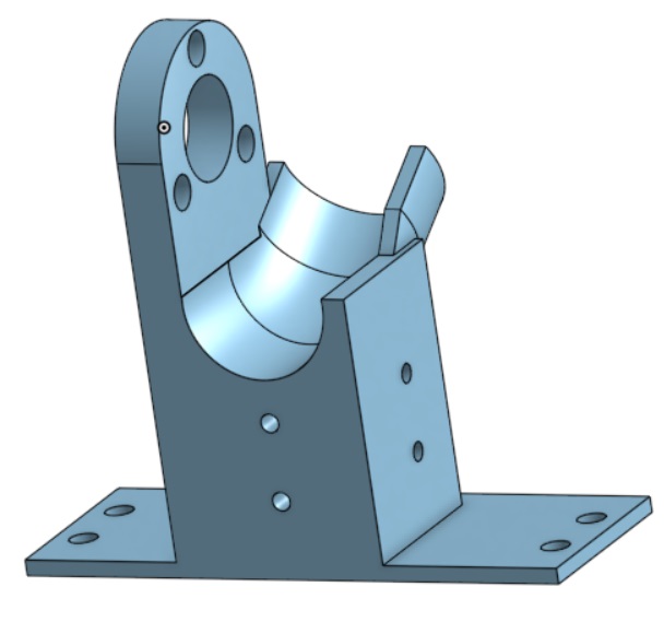 |
Flywheel Mount (FlywheelMount.stl) |
 |
Flywheel (FlywheelLong.stl). This piece should be printed with a 100% fill to maximize the moment of inertia. |
 |
Flywheel Cap (FlywheelCap.stl); |
 |
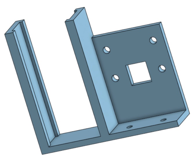
Raspberry Pi Mount (RaspberryPiMount.stl) |
 |
Motor Controller Mount (MotorControllerMount.stl). You will need 3 of these. |
 |
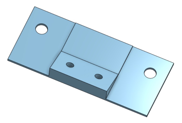
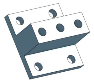
Turntable Motor Mount (TurntableMotorMount.stl). |
 |
Power Distribution Module Mount (PowerDistMount.stl). You will need 2 of these. |
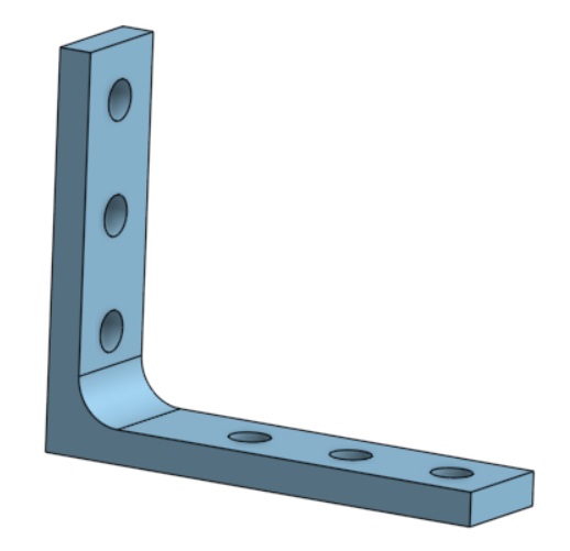 |
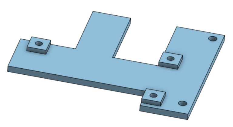
Pi Mount Bracket (PiMountBracket.stl). |
 |
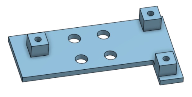
Pi Camera Mount (PiCameraMount.stl). |
 |
Pi Camera Bracket (PiCameraBracket.stl). |
 |
Arduino Clamp (ArduinoClamp.stl). The main Arduino attaches to this and it attaches to the Raspberry Pi. |
 |
Auxiliary Arduino Mount (ArduinoMount.stl). This is the mount for the auxiliary Arduino. |
 |
Swivel Wheel Mount (SwivelWheelMount.stl). |
The following is a list of commercially available parts that you will need along with links as to where you can source these parts:
|
|
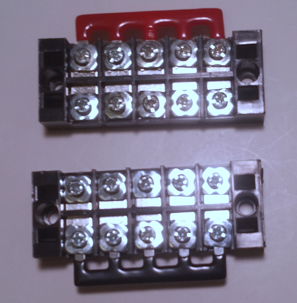
These are the power distribution modules, one for positive and one for negative. You can buy them in packs of 5 here. |
|
|
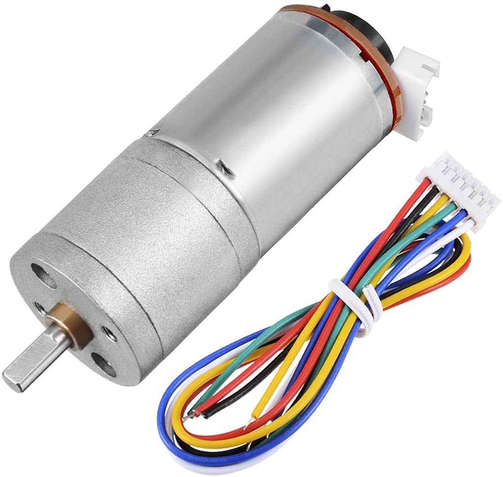
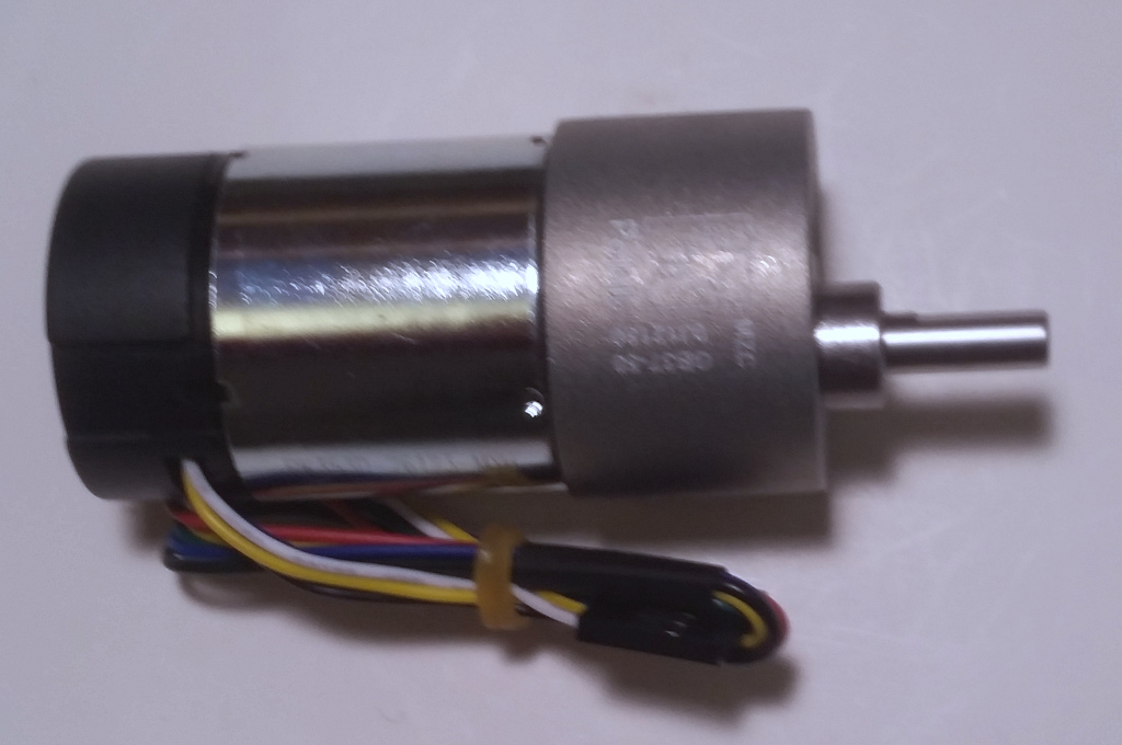
This is the drive motor. You can find it here. Note that I have chosen the 50:1 gear ratio, but there are a number of other ratios available which will make the robot move faster or slower. You will need 2 of these. |
|
|
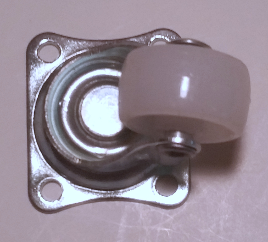
The Swivel Wheel is the third wheel at the back of the robot and can be found here. |
|
|
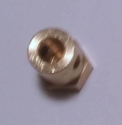
This is a 6mm bore hex coupler which attaches to the drive motor shaft and the wheel. You will need 2 of these and they can be found here. |
|
|
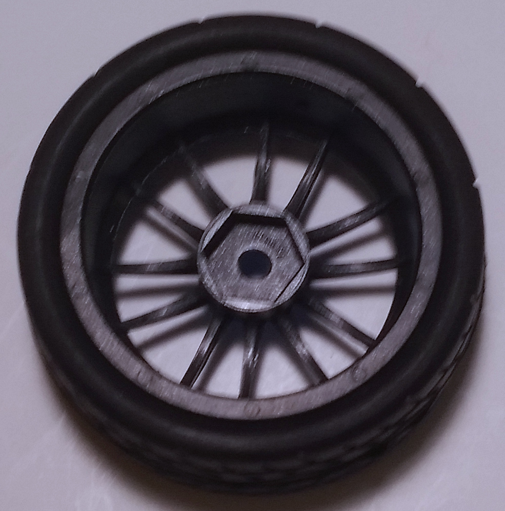
This is a Wheel for the robot. You will need 2 of these and they can be found here. |
|
|
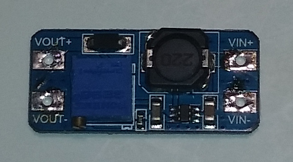
This is a Step Up Voltage Regulator. I am using 7.2v NiMh batteries (which range from 7v to 8v) to power the robot but we want to power 12v motors. To accomplish this you will need 3 of these regulators which can be found here. If you choose to use a 12v battery (e.g. LiPo) then you will not need these. However with 12 volts you will need one step down regulator to provide the proper voltage for the LED light on the camera which requires xxx volts. |
|
|
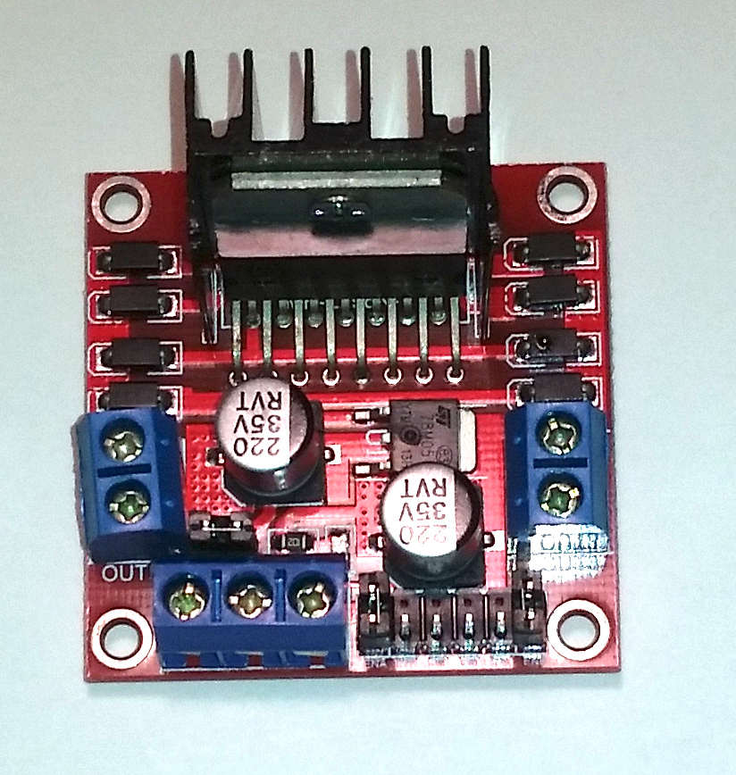
This is the Motor Controller we will be using. Each of these can control 2 motors up to 2 amps each. We will need three of these and they can be found here. |
|
|
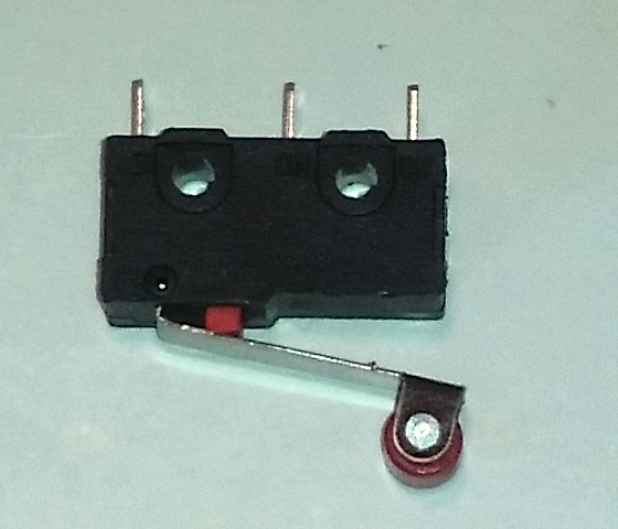
This is a Limit Switch which is used to turn the turret motor off when the turret has reached it’s maximum travel. You will need two of these and they can be found here. |
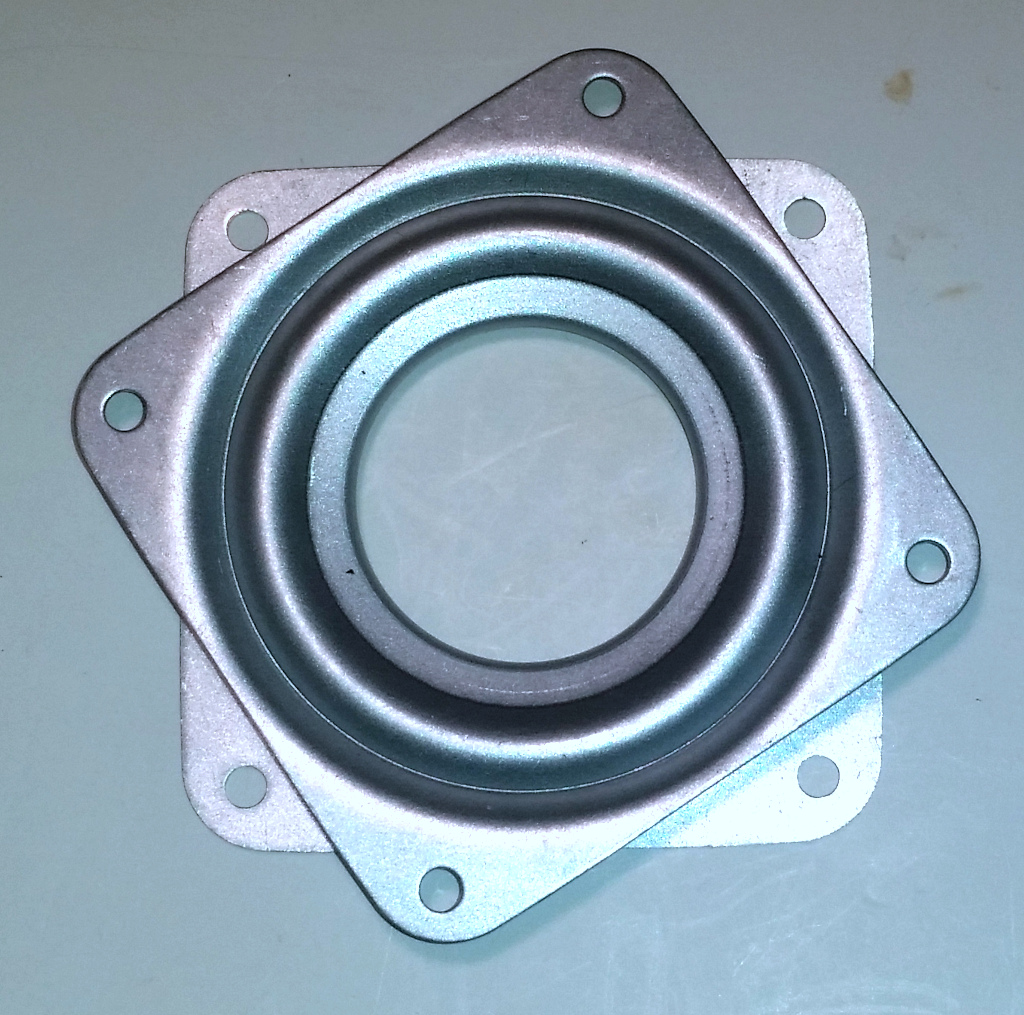 |
This is the Turntable Bering that allows the turntable to rotate and can be found here. |
|
|
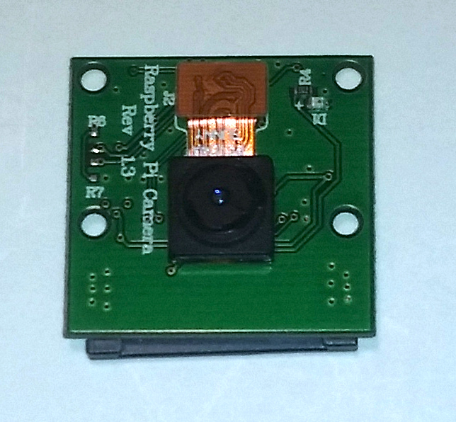
This is the Raspberry Pi Camera which we will be using for vision tracking. Be sure that you get version 1.3, 5MP version, not the newer version 2, 8MP version. These cameras can be purchased from many source like here. You will also need a 50 cm Camera Cable which you can find here. |
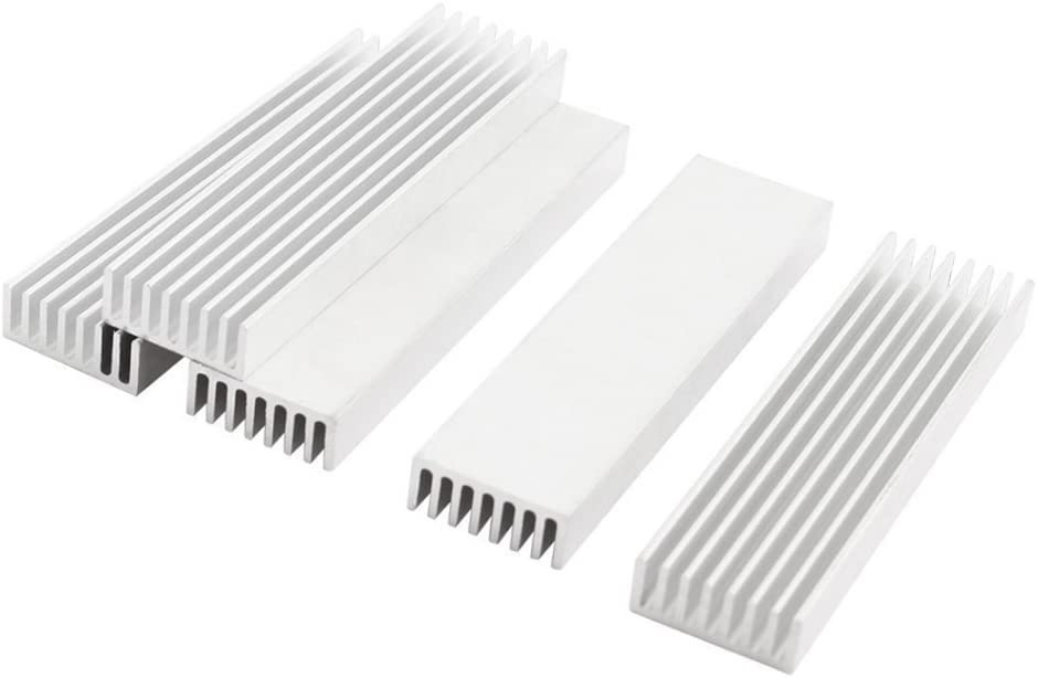 |
These are LED Heat Sinks for the green LED light. Each heat sink is 10 cm long and must be cut in half to provide the heat sink for a single LED. They can be found here. |
|
|
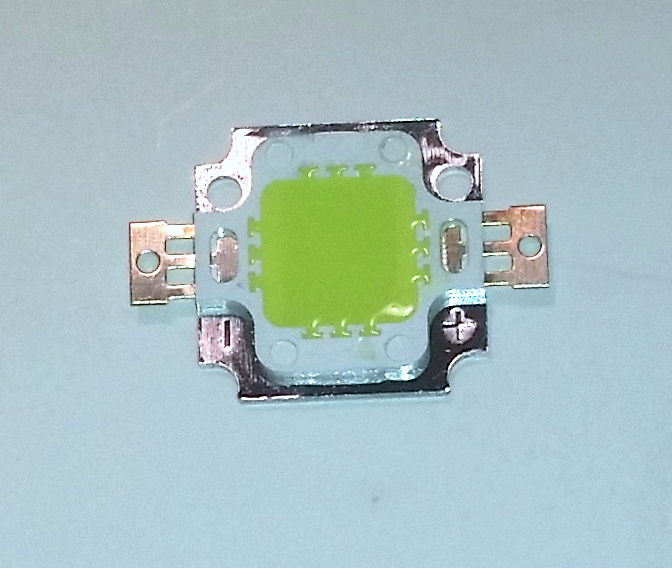
10 watt Green LED for vision tracking. These can be found here. Be sure to select the green color (520-523 nm). |
 |
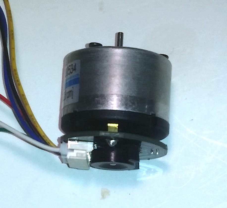
The Feeder Motor is a 55 rpm motor which drives the Nerf Ball Feeder Rotor. This can be found here. |
|
|
Shooter Motor. This can be found here. |
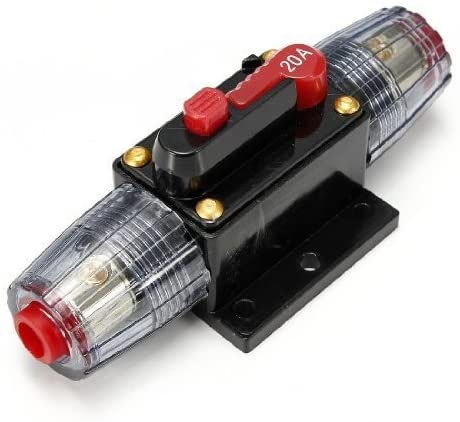 |
20 amp Circuit Breaker which can be found here. |
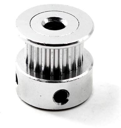 |
The Timing Belt Pully attaches to the Turntable Motor shaft and can be found here. |
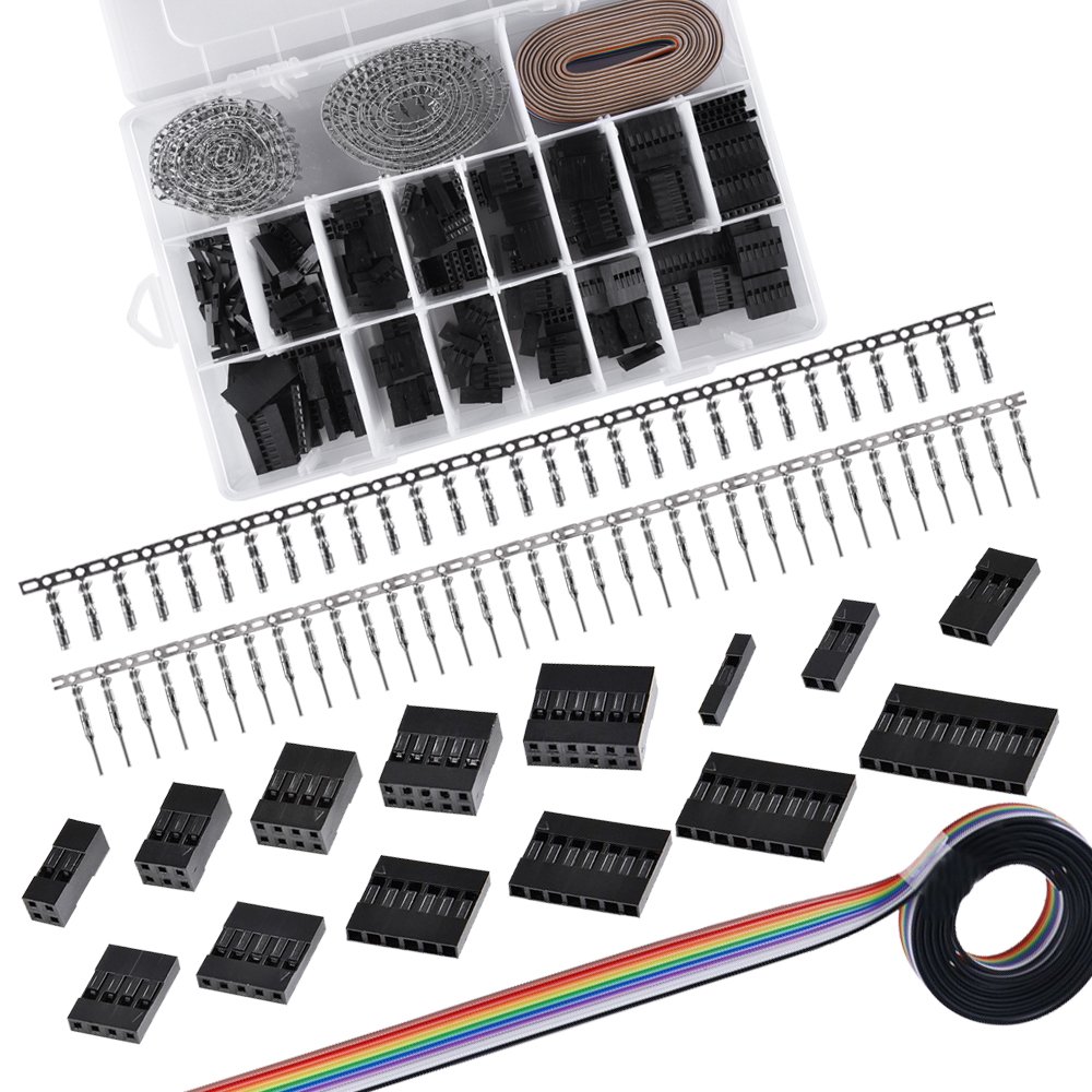 |
You will be needing some both Male and Female Crimp Connectors and some 0.1 inch housings. You can purchase them separately or get a kit like this which can be found here. |
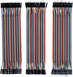 |
You will also need some Dupont Jumper Cables. You can make these using your crimp connector kit, but you can also purchase them premade here. You can easily remove the 1×1 housings so that you can insert the connectors into a housing of your choice. |
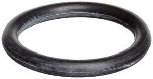 |
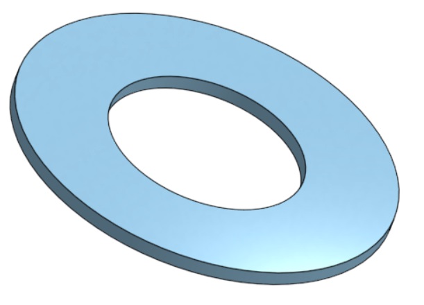
This is a 7/8″ ID, 1-1/8″ OD, 1/8″ width O-Ring which is used for the shooter Flywheel. |
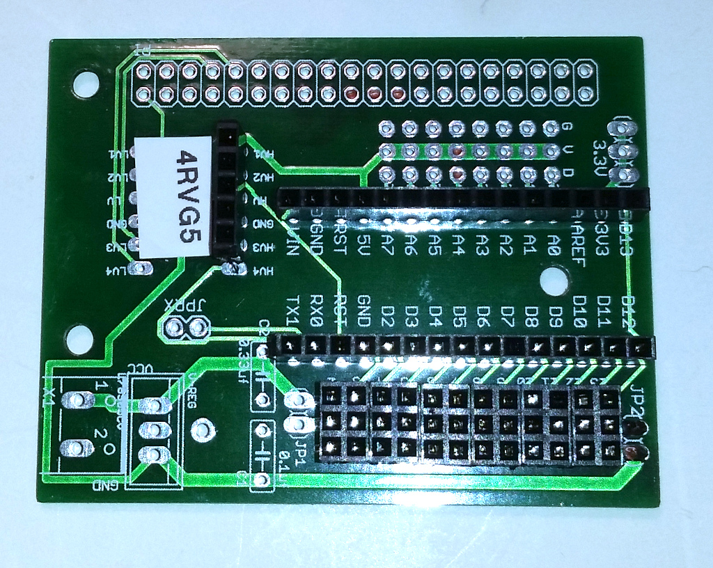
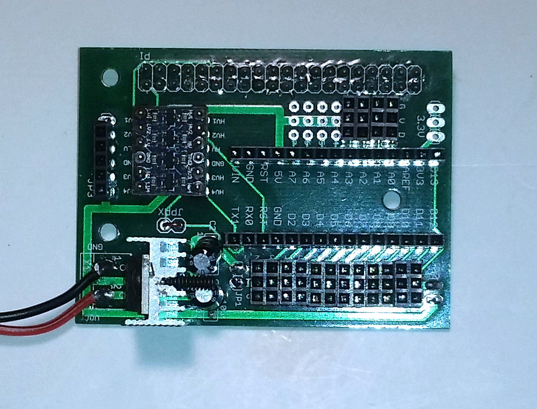
The following are two custom boards that you will need. I have a small number of these boards available. Contact me if you need some.
|
|
The Auxiliary Arduino Board provides a second Arduino to control the drive motors and read their quad encoders. |
|
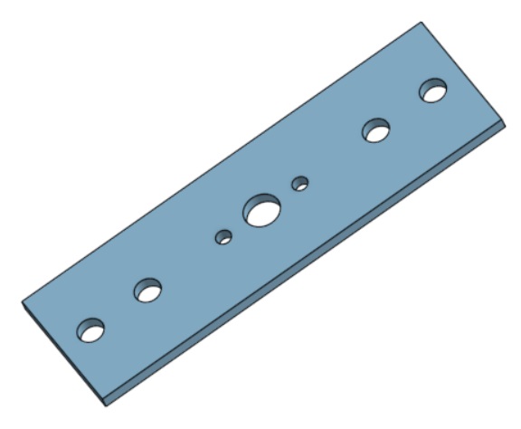
|
The Arduino Board connects the main Arduino to the Raspberry Pi and provides the 5v needed to operate the Pi and the Arduinos. |