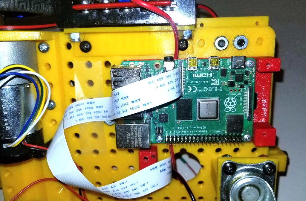
We are now ready to do the final assembly and wiring. First attach the Raspberry Pi to the Pi Mount on the bottom of the robot using four 3/8 inch 4-24 sheet metal screws and attach the Pi Camera Cable to the Pi as shown below:
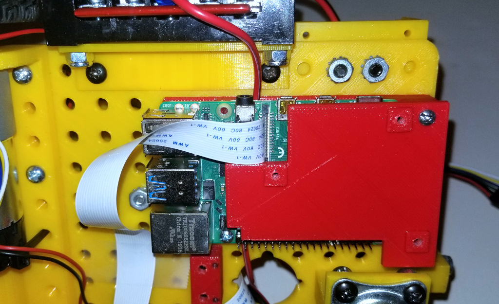
Now attach Microcontroller Mount using a single 3/8 inch 4-24 sheet metal screw as shown:
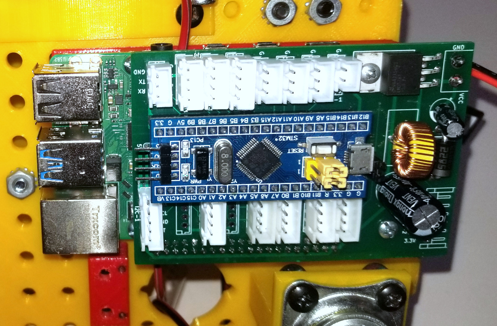
Now, attach the microcontroller board using three machine screws as shown:
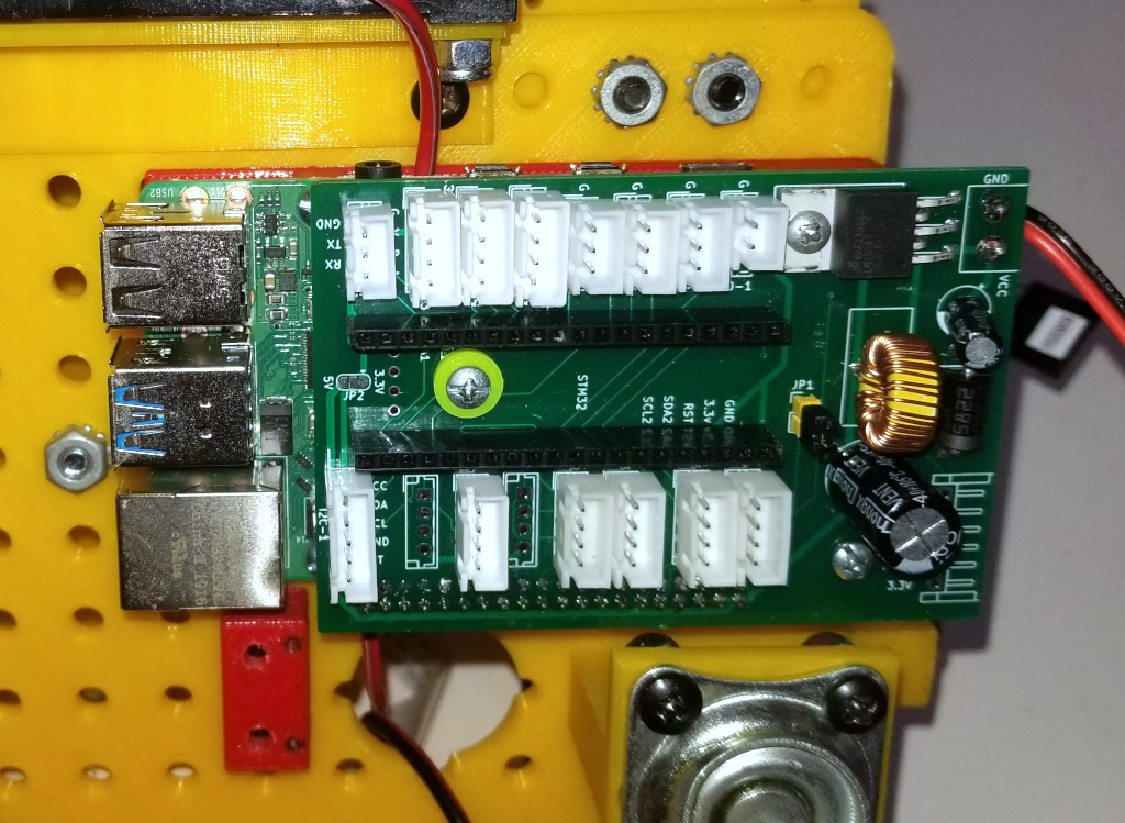
Then insert the STM32 microcontroller into the socket as shown:
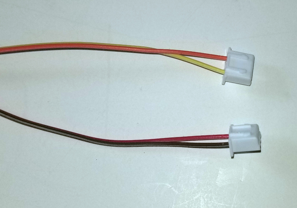
Now, prepare the wires for the limit switches. Cut two 14 inch long pieces of 2 wire 28 gauge ribbon wire and attach the connectors to the end as shown. Note that we use 3 pin connectors here but attach only two wires to each.
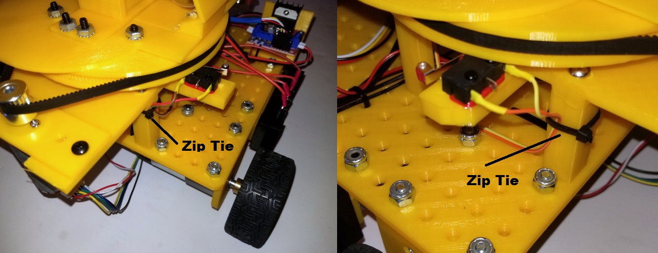
Then solder the other end of the wires to the limit switches as shown below, the order of the wires is not important here. Note the zip ties which attach the wires to the turret. These zip ties provide strain relief for the solder joints.
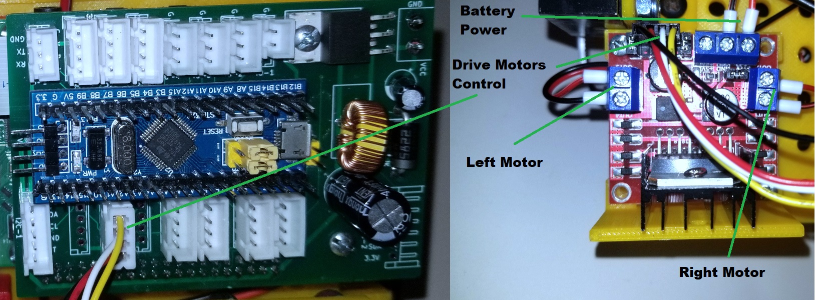
Now we are going to attach and wire the three Motor Controllers. Attach a Motor Controller for the Drive Motors to the underside of the chassis. Then attach the power and control wires as shown:
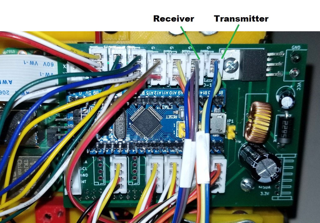
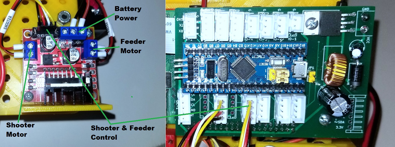
Next we attach a Motor Controller that will control the Feeder and Shooter motors and attach the power and control wires as shown:
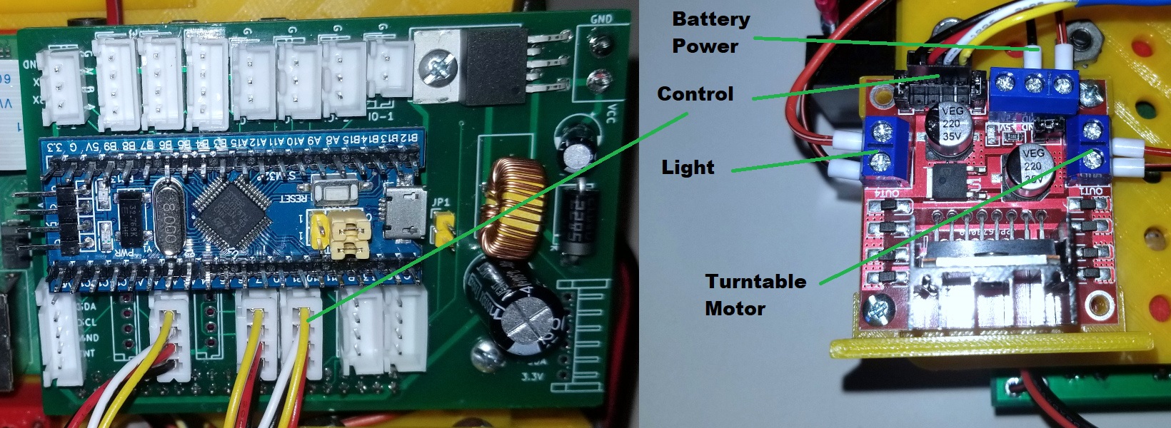
Finally, attach the third Motor Controller for the Turntable and Light and connect the power and control wires as shown:
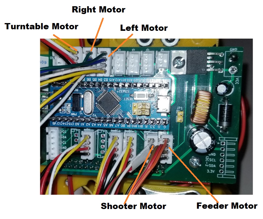
Now connect the encoder lines from the 5 motors as shown:
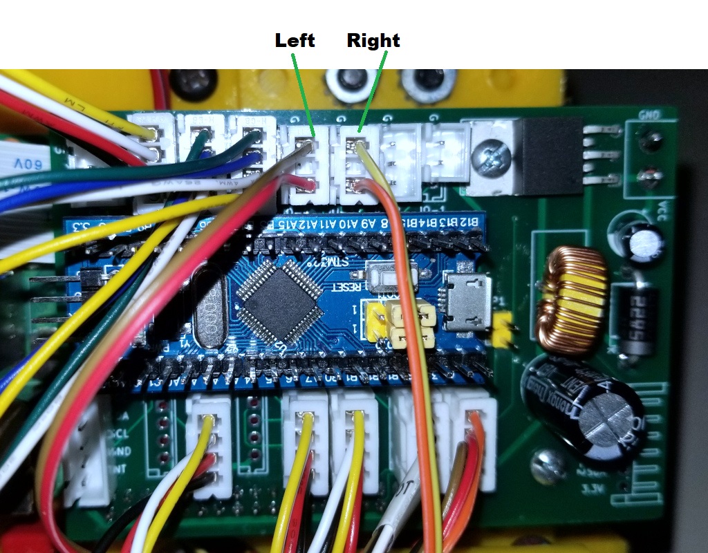
Now connect the left and right Limit Switches as shown:
Now connect the Beam Break lines as shown: