The Nerfbot is a robot which has a nerf ball shooter mounted on a turret which is controlled by a camera. This is the robot that is used in the Nerfbot tutorial. Most of the parts are 3D printed and the following chapters describe it’s construction and wiring.
Before we begin, lets take a look at the electronics. The robot is controlled by a Raspberry Pi which is connected to a Microcontroller Board via an I2C connection. The Microcontroller we are using is a STM32F103C8T6 in a single board commonly know as a Blue Pill. The Microcontroller Board layout is shown below:
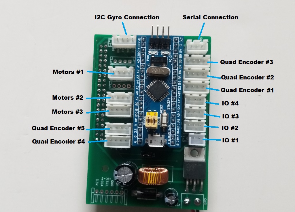
There are three Motor Connectors, each of which can drive two motors. There are five connectors for Quadrature Encoders. There are four general purpose IO connections. Finally there is one I2C connector for connection to the Gyro and a Serial Connector used only for debugging. Let’s take a look at each of the connector types in detail:
This is one of the Quadrature Encoder connection showing each pin’s function.

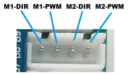
Each of the Motor Connectors can control two motors. The pin connections are as shown.
The IO Connector can be configured as either an input or output. The pin connections are as shown.
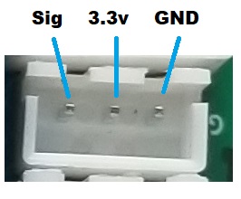
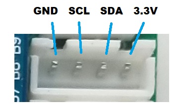
The Gyro Connector is used to connect the Microcontroller to the Gyro via an I2C connection. The pin connections are as shown.
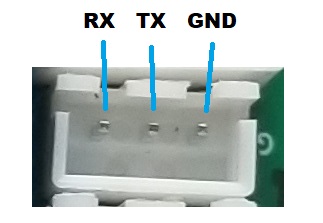
The Serial Connection allows you to connect the Microcontroller to a serial port on your computer. This is only used for debugging. The pin connections are as shown.