The Drive Subsystem performs the same function as its counterpart in the Minibot tutorial, namely it will control the two drive motors. In fact you may want to refer to your code for that previous robot as an aid.
The motors for this new robot will use the same PWMMotor class that you used previously.
|
1 2 3 4 |
robotCore.PWMMotor.PWMMotor( int pwmPin, int dirPin ) |
You are, of course, going to need the pin numbers to use:
|
1 2 3 4 |
private static final int k_leftMotorPWMPin = Device.M1_1_PWM; private static final int k_leftMotorDirPin = Device.M1_1_DIR; private static final int k_rightMotorPWMPin = Device.M1_2_PWM; private static final int k_rightMotorDirPin = Device.M1_2_DIR; |
With this information, you should now be able to create your Drive Subsystem class. Once you have done that, create an Arcade Drive command and get your robot driving with a joystick. Remember to set your Arcade Drive command as the Drive Subsystem’s default command.
Once you have your robot driving you will want to use the wheel encoders to calibrate the speed as we did in the MiniBot tutorial. For this robot however, we are using a different kind of encoder called a Quadrature Encoder. We will still use the Encoder class, but we will set the type to EncoderType.Quadrature. These encoders use this constructor:
|
1 2 3 4 5 |
robotCore.Encoder.Encoder( EncoderType type, int pin1, int pin2, ) |
You will need the pin numbers:
|
1 2 3 4 |
private static final int k_leftEncoderIntPin = Device.Q1_INT; private static final int k_leftEncoderDirPin = Device.Q1_DIR; private static final int k_rightEncoderIntPin = Device.Q2_INT; private static final int k_rightEncoderDirPin = Device.Q2_DIR; |
Once you have created instances of your encoders, remember to set them as the feedback devices for your motors.
Finally, create setPower and setSpeed functions to control the two motors. You can look back at the Robot Java tutorial if you need help in remembering how to do this.
You should now be ready to tune the speed of your drive motors. Again, you can look back at the Minibot tutorial to refresh your memory of how to do this but the following are the basic steps involved:
- You should create a Calibrate Drive command and tie it to a button.
- Using this command, drive the motors at full power (using setPower) and log the speed for the left and right wheels. This will tell you the maximum possible speed for each of the motors.
- First set the F term of the PID controller for each of the motors so that they are running at about 75% of the maximum speed (using setSpeed).
- Next add a P term and increase it until you see the speeds become unstable, and then back off a bit.
- Finally add an I term and increase it until you see the speeds become unstable, and then back off a bit. Remember to set an appropriate IZone.
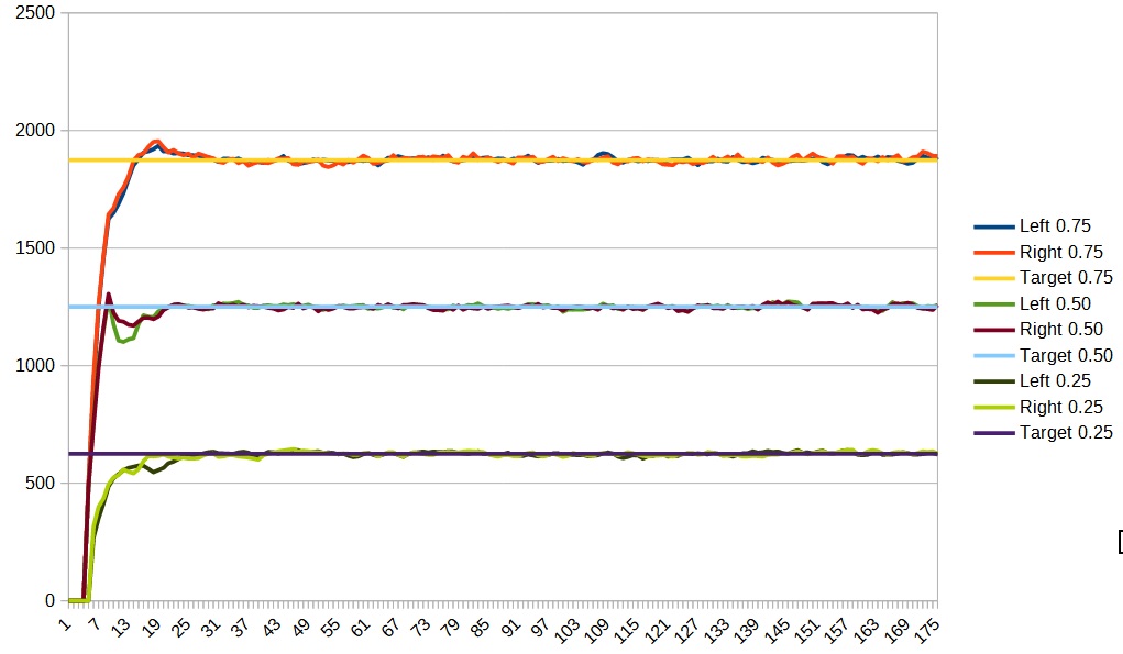
- Once you have it tuned for 75% speed, check the tuning at 50% and 25%. Since it is not possible to have ideal F, P and I terms at all speeds, only change the P and I terms if there are significant problems at those speeds.
In my case, I found that the max speed was around 2500 and the final calibration graphs appeared as follows:
Once you have your drive motors calibrated, you can change your Arcade Drive command to use speed instead of power if you like.