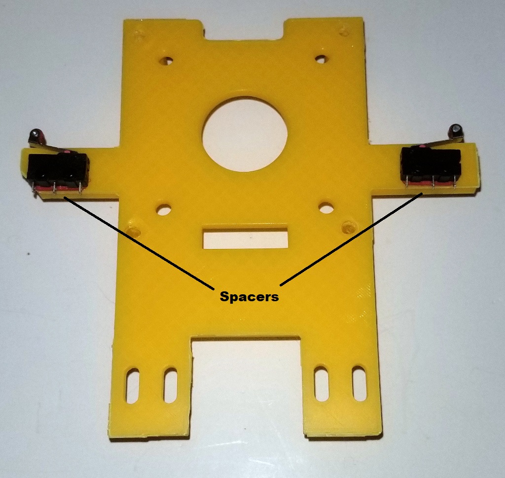
Attach the two Limit Switches to the top of the Turntable Bottom Plate using four 2-56 machine screws and four Limit Switch Spacers as shown below. Note the Limit Switch Spacers placed between the limit switch and the plate. Also pay attention to the orientation of the limit switches.
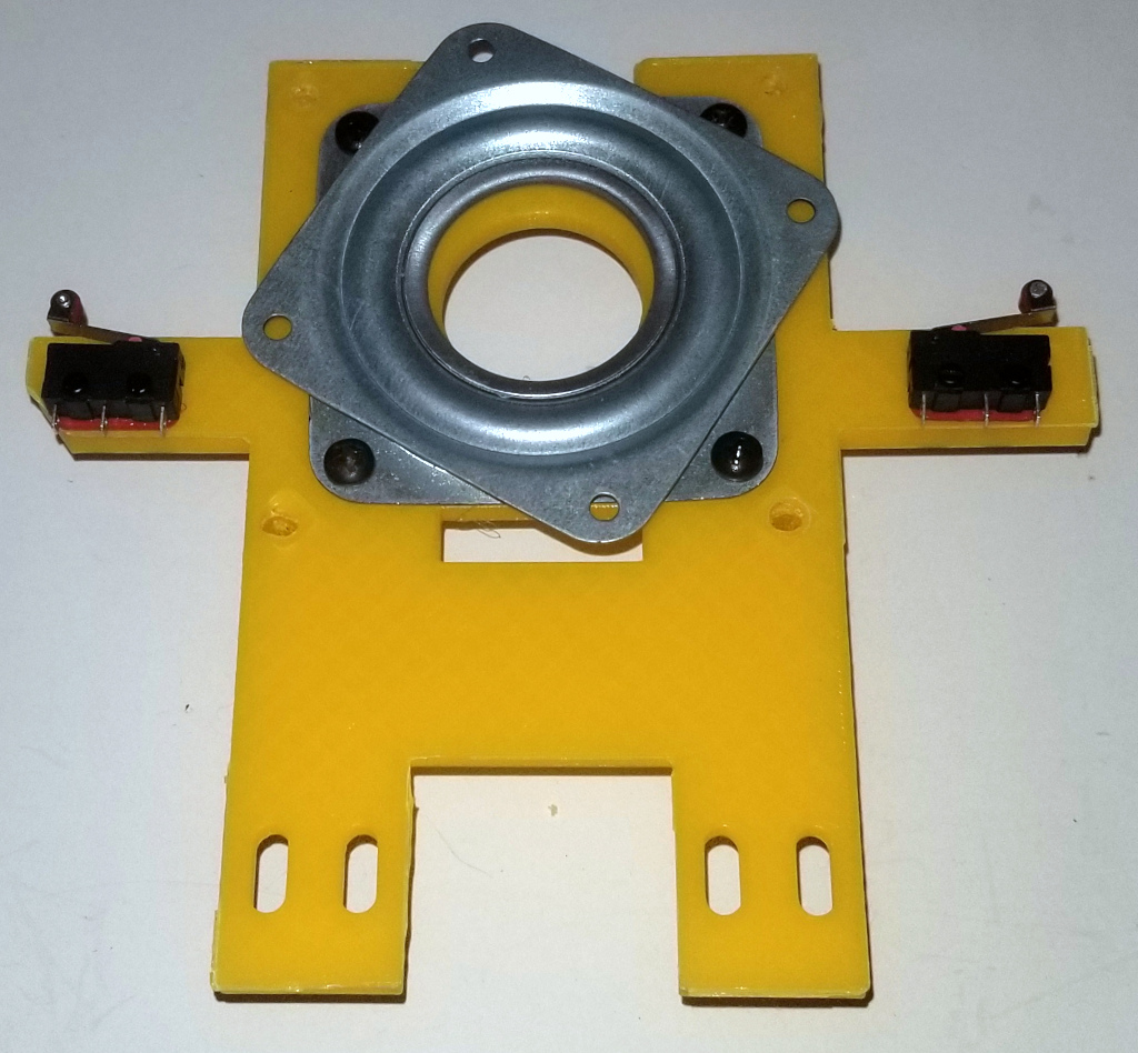
Using the 4 Turntable Spacers, attach the Turntable Bering to the top of the plate with four 1/2 inch 8-32 machine screws as shown below:
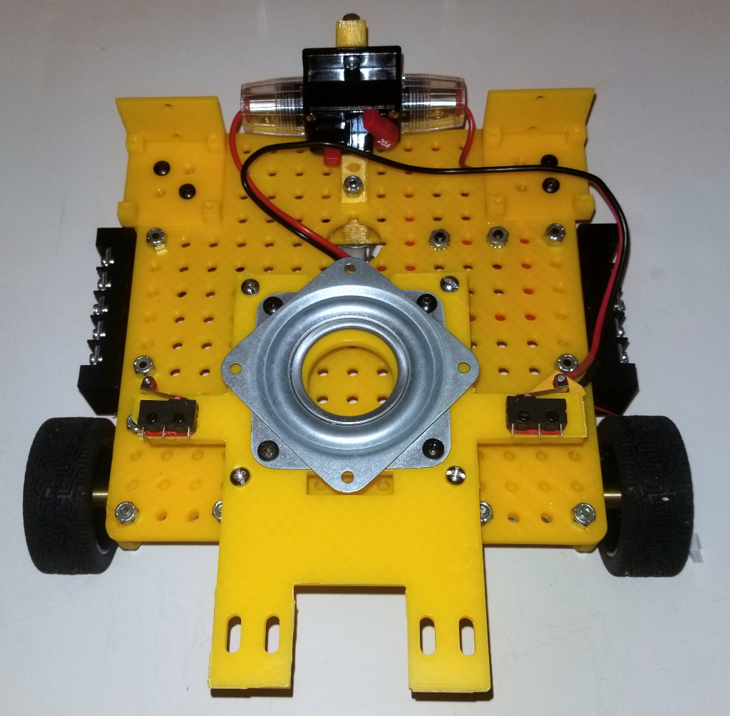
Next, attach the Turntable Bottom Plate to the Chassis. Use two 2-1/2 inch 8-32 bolts on the front and two 2-1/4 inch 8-32 bolts on the back as shown:
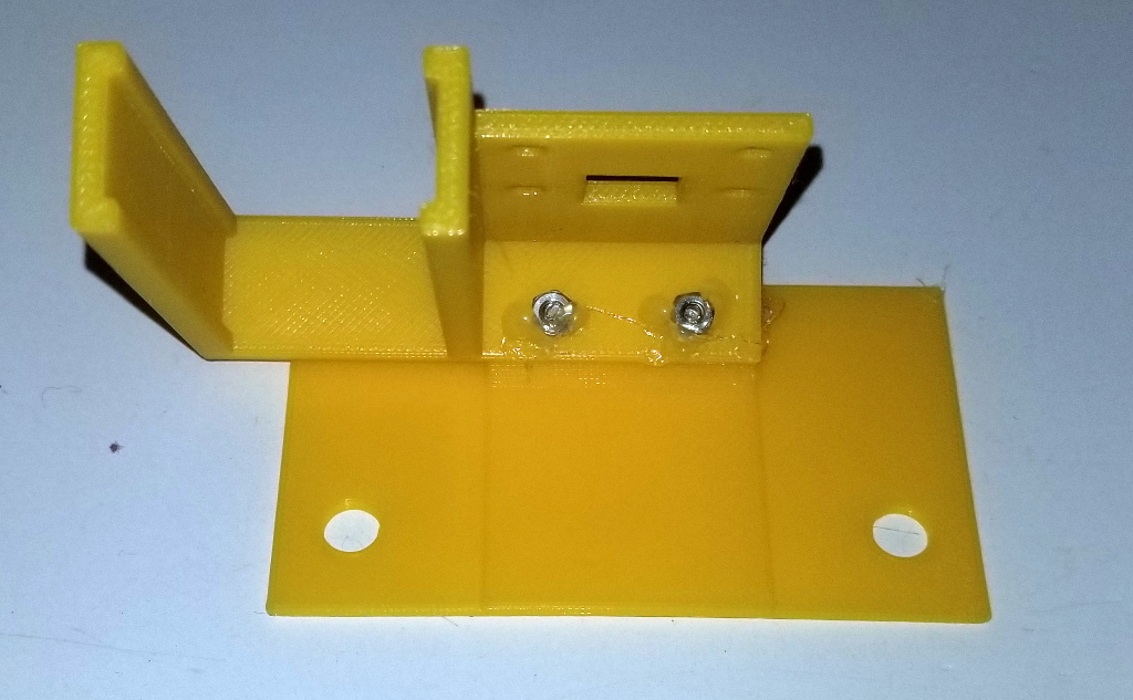
Now attach the Pi Camera Bracket to the Pi Camera Mount using two 1/4 inch 2-56 screws as shown:
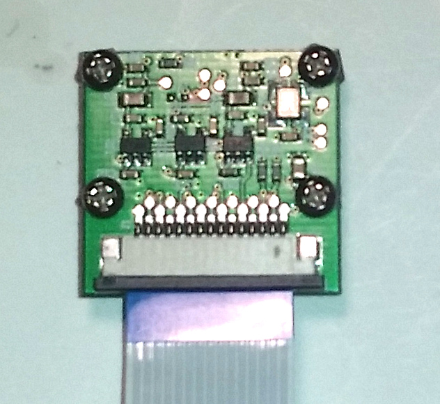
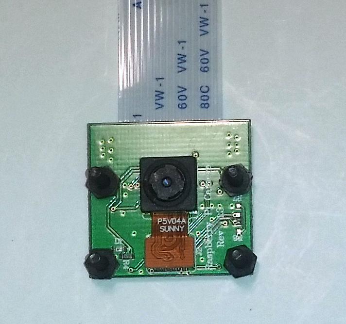
Next we will assemble the Pi Camera Module. Attach a 50 cm Pi Camera Cable to the camera and then insert four 2-56 machine screws as shown below. Here I have used nylon (plastic) nuts to fasten the screws. These will act a spacers between the camera and the mount. It is not essential that these be nuts, you can also just use plastic spacers but using nuts will make it easier to assemble. It is important that you do not use metal nuts as they might short out traces on the PC board.
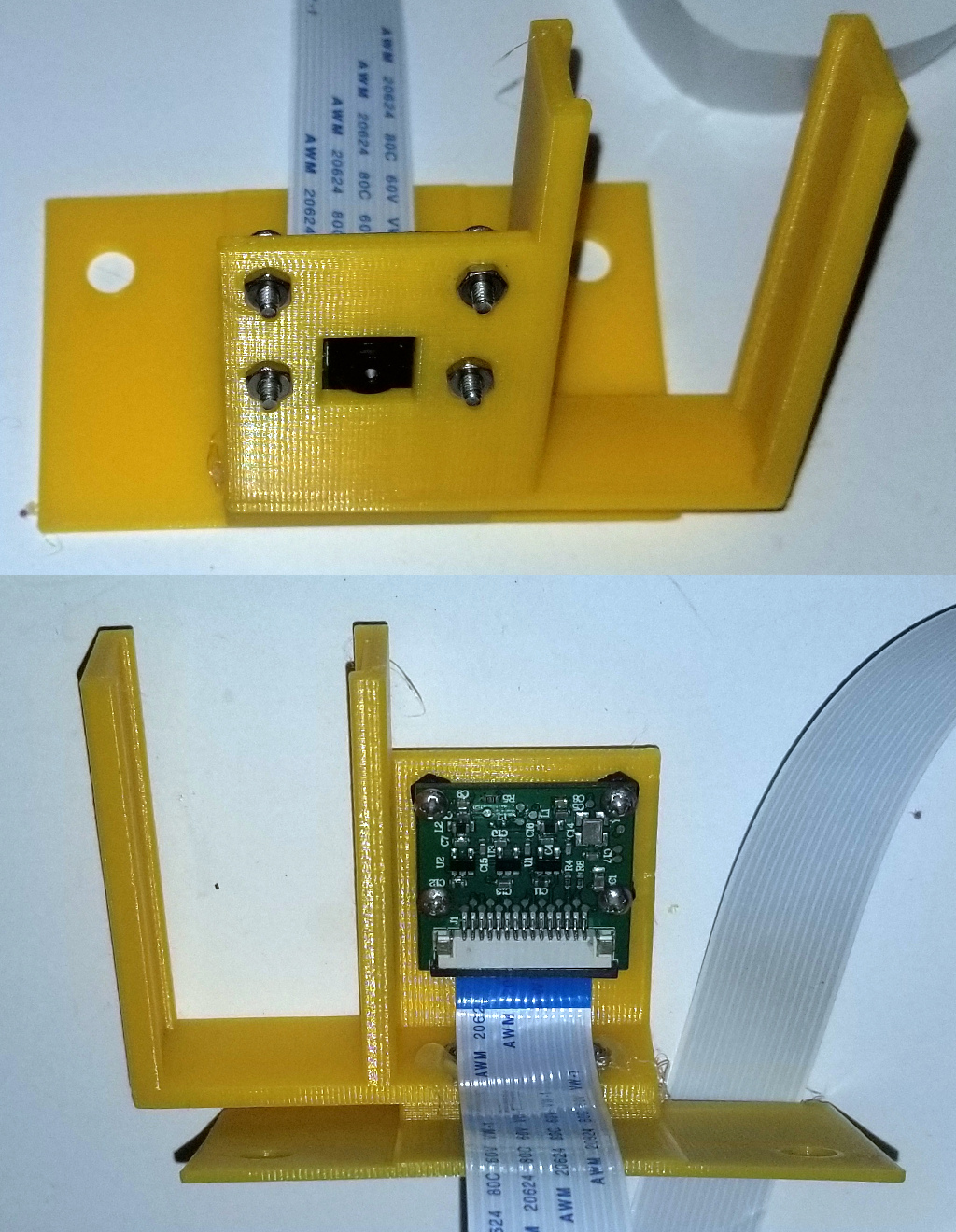
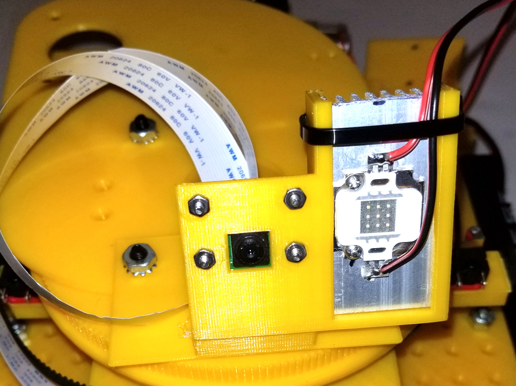
Now mount the camera on the Pi Camera Mount as shown:
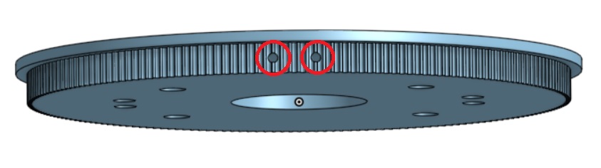
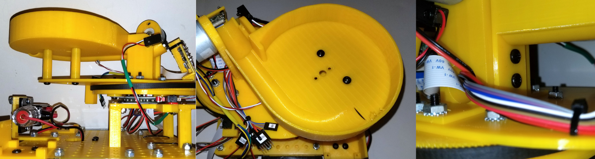
Now, using a 4-40 tap, tap the two holes in the Turntable Gear as shown below:
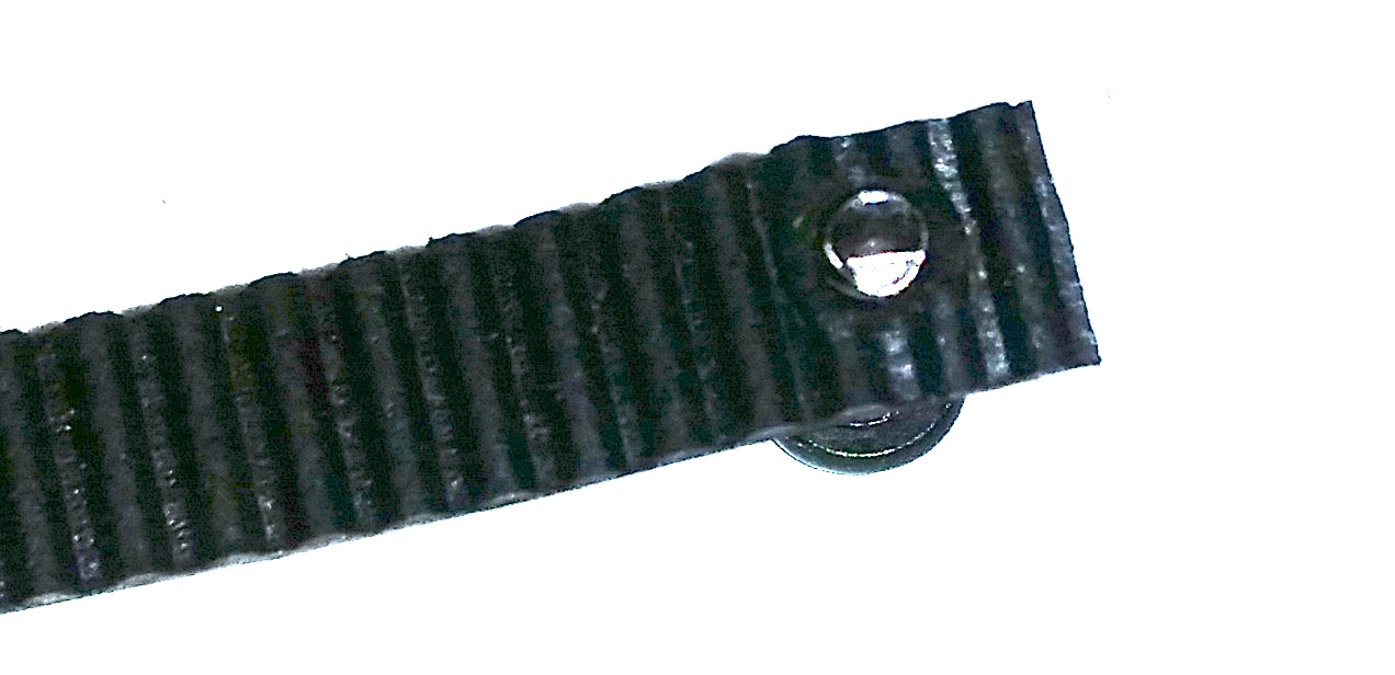
Cut a 43.5 cm length of 6 mm wide, 2 mm pitch Timing Belt and punch or drill a hole in 4 mm from each end large enough to thread a 4-40 screw. The hole should be centered in the second grove from the end, as shown below.
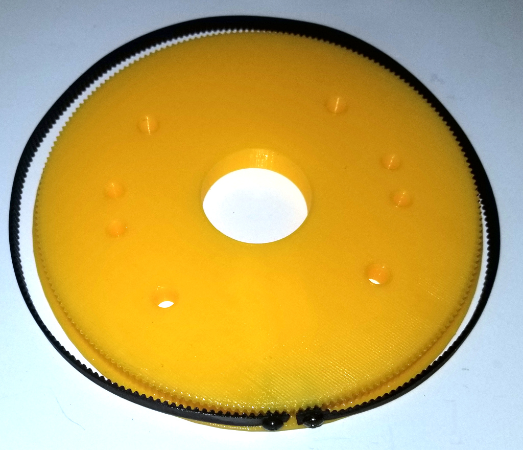
Now attach the timing belt to the Turntable Gear using two 1/2 inch 4-40 bolts:
Now using 1 inch 8-32 bolts place the Turntable Plate onto the Turntable Bottom plate followed by the Turntable Gear as shown below. Note the direction of the gear and make sure that the point at which the belt is fastened to the gear is at the rear. Also make sure that the lip on the Turntable Gear is on top.
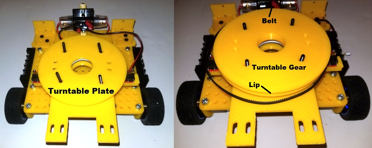
Then position the Turntable Top Plate and the Pi Camera Mount as shown and fasten with lock nuts:
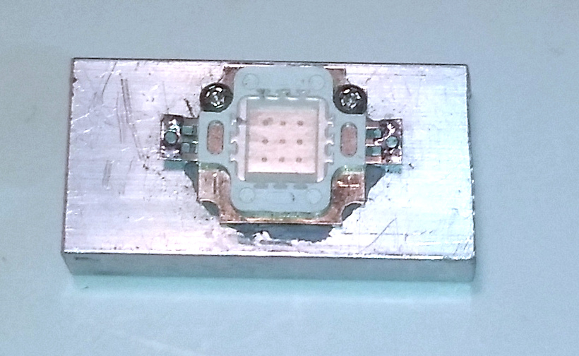
Now cut one of the 10 cm LED Heat Sinks in half so you have a 5 cm piece. Then drill holes in the heat sink and attach the Green LED to the heat sink as shown below:
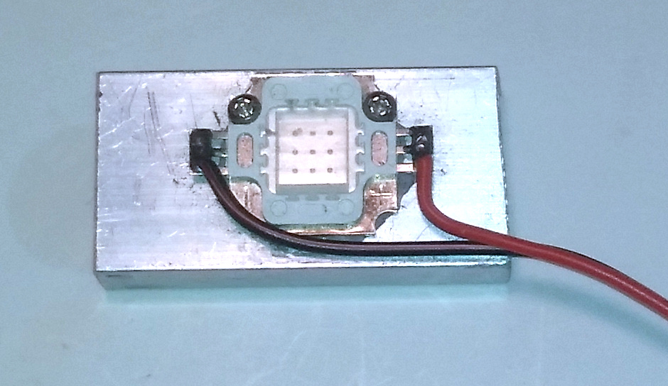
Next cut a 16 inch length of red and black 20 gauge wire and solder one end to the plus and minus terminals of the LED. Take care to solder the black wire to the minus terminal and the red wire to the positive terminal:
Then slide the heat sink into the slot on the Pi Camera Mount as shown below. Note the zip-tie attached to the top.
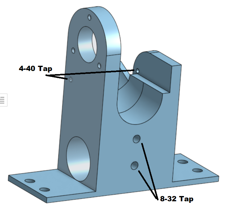
Tap the four holes in the Flywheel Mount as shown below:
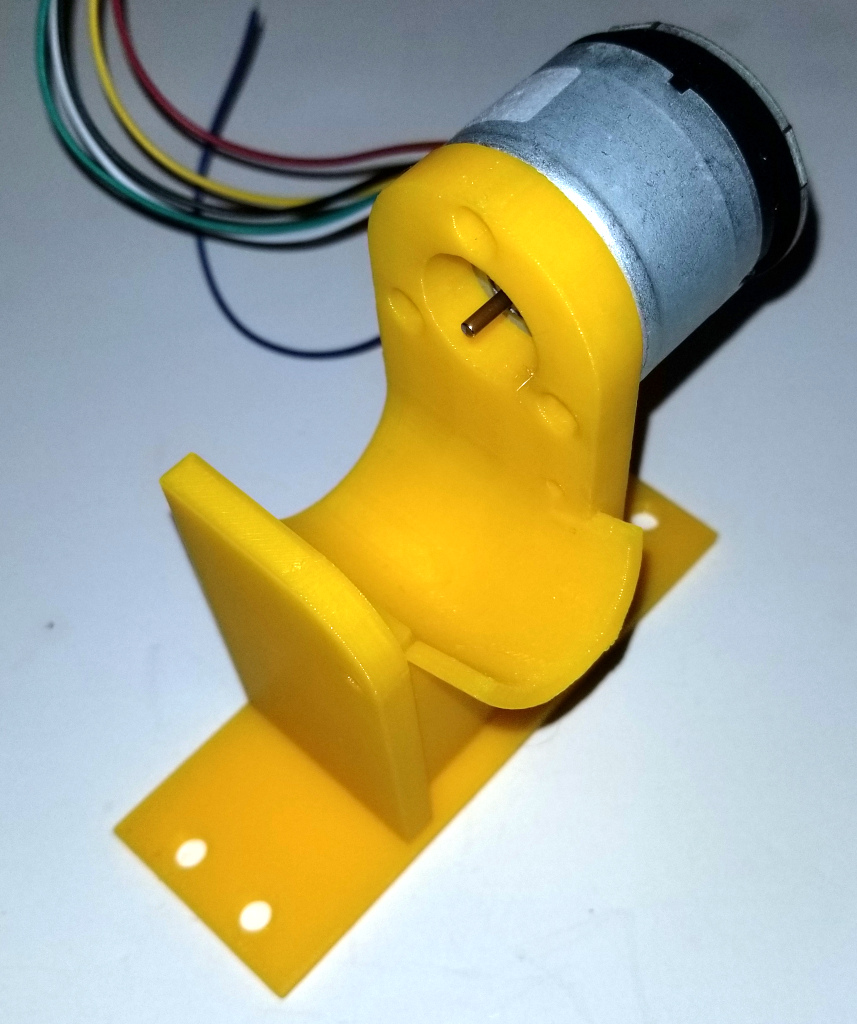
Now attach the Shooter Motor to the Shooter Mount using three 3mm M2.5 screws as shown:
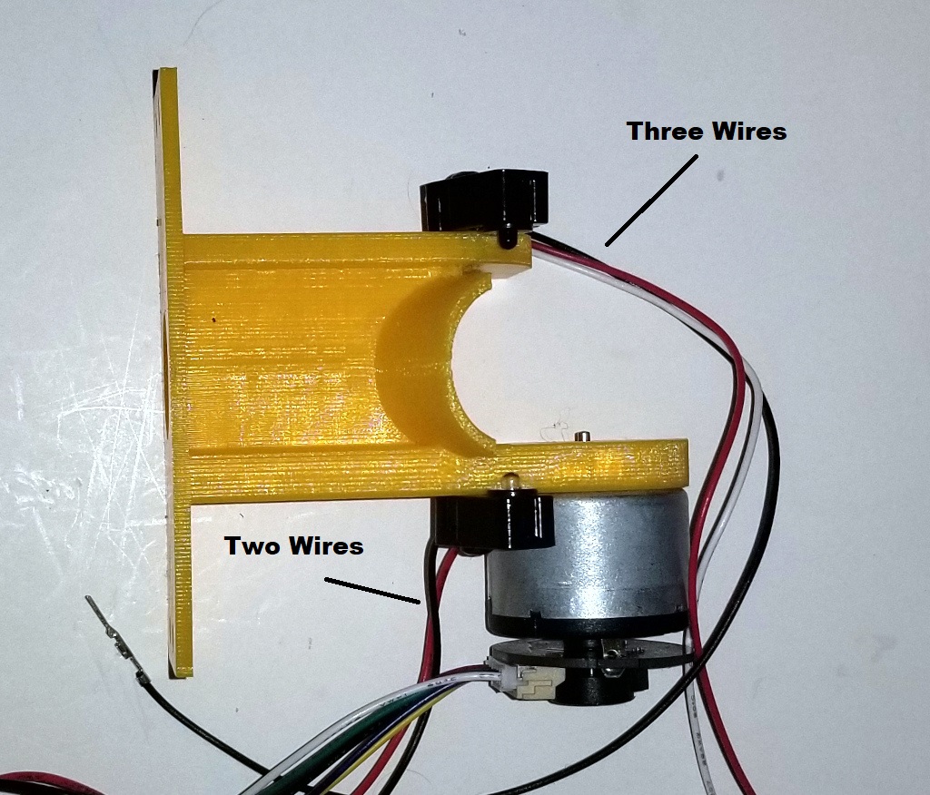
Then attach the two Beam Break Sensors using two 4-40 bolts as shown. Note that the sensor with three wires goes on the left:
Now we need to prepare the wiring cables which will connect the motors and sensors on the turret with the electronics on the chassis. We want to do this now because we will need to feed those cables down to the chassis and it will be easier to do this now rather than later.
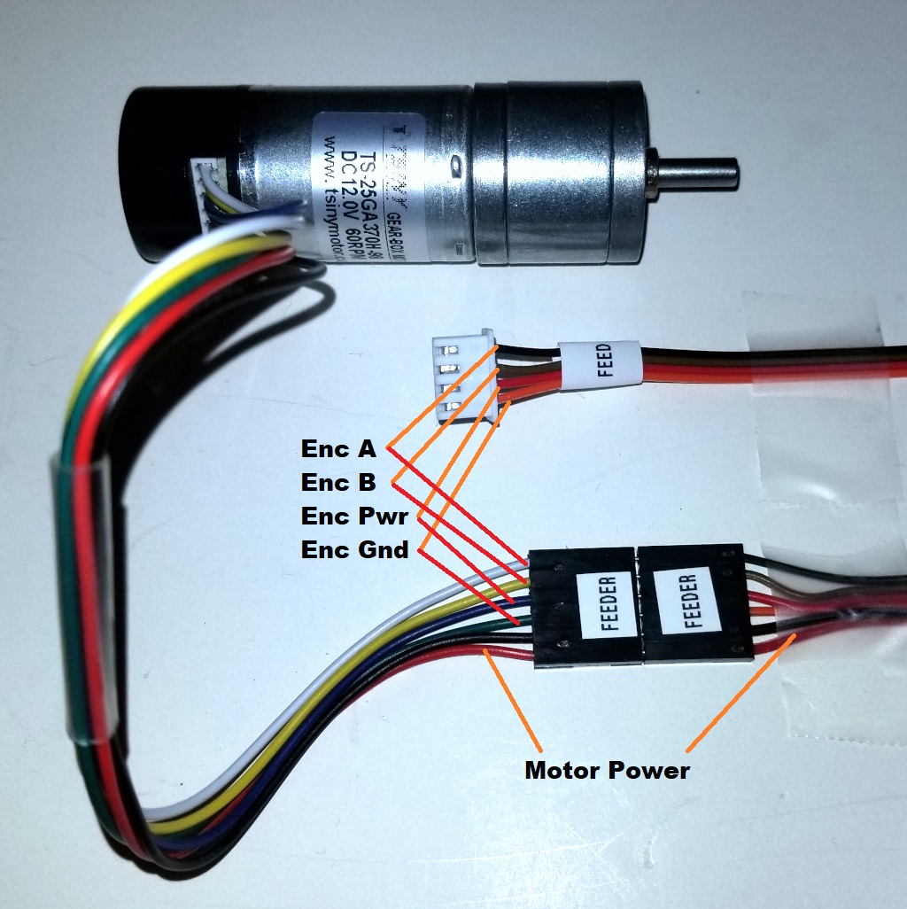
For the Shooter Motor we will need a 4 wire cable to read the quadrature encoder as well as a 2 wire cable for the motor power. Cut an 18 inch length of four conductor 28 gauge ribbon wire and a 16 inch length of 24 gauge red and black power wire. Then crimp connectors on each end of the two cables as shown below. Take particular care to connect the wires in the correct order as show:
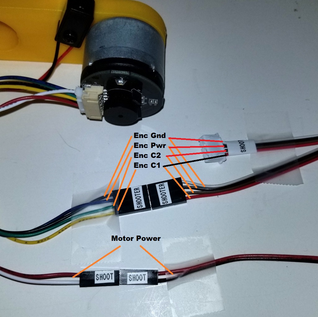
I highly recommend that you label both ends of the cables so that you can identify which cable is which later when connecting the wiring to the electronics.
Now for the Feeder Motor cut a 18 inch section of 4 wire 28 gauge ribbon wire and a 16 inch section of 24 gauge red and black power wire. Then crimp connectors onto either end taking care of the order of the wires as shown below:
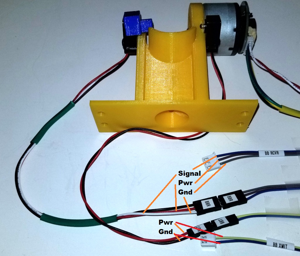
For the Beam Break Sensor, cut an 18 inch three wire 28 gauge ribbon wire and an 18 inch two wire 28 gauge ribbon wire. Attach connectors to each end of the cables taking care to make sure of the order as shown below;
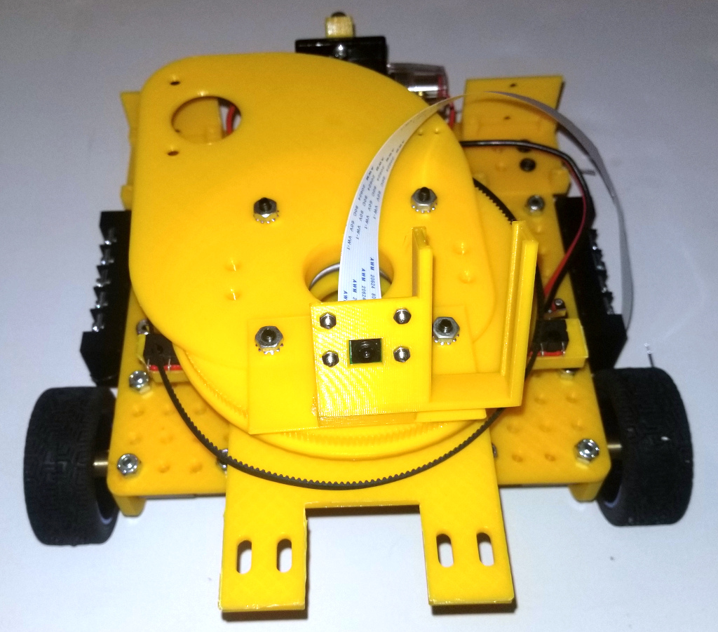
Now feed the camera cable, the light power wire and all of the cables you just made through the hole on the side of the Shooter Mount and down through the hole on the Turntable Plate. Then attach the Shooter Mount using four 1 inch 8-32 bolts as shown:
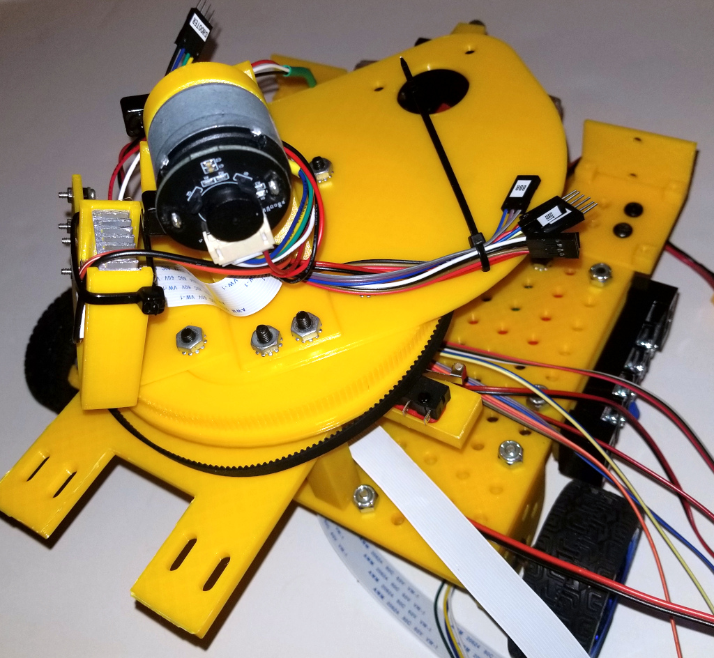
Finally zip-tie all of the cables to the tie holes a shown above.
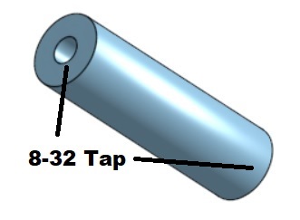
Now, using a 8-32 tap, tap both ends of the two Feeder Supports:
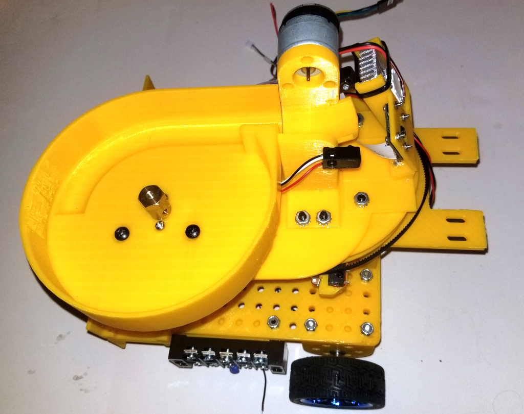
Then attach the Feeder to the turntable using six 8-32 bolts as shown:
Now attach the Feeder Motor using two 4 mm M3 screws as shown:
Next attach the 6mm bore hex coupler to the Feeder Motor as shown below:
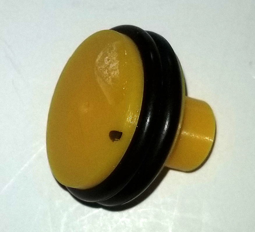
Now glue the Flywheel Cap to the Flywheel using epoxy and after the glue has dried attach the two O-Rings as shown below:
You may then want to balance the Flywheel. This can be done by inserting a 3mm rod through the center hole and then placing it between two supports to see how the wheel is balanced as shown below:
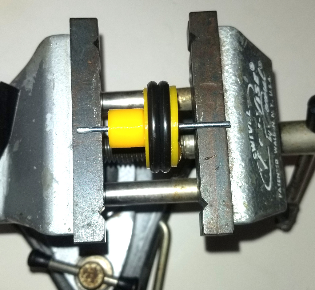
Once you have found the portion of the wheel which is heavier (it will rotate to the bottom) you can add extra material on the opposite side to balance the wheel. This material can consist of some additional epoxy glue, or in extreme cases you can glue on a small washer.
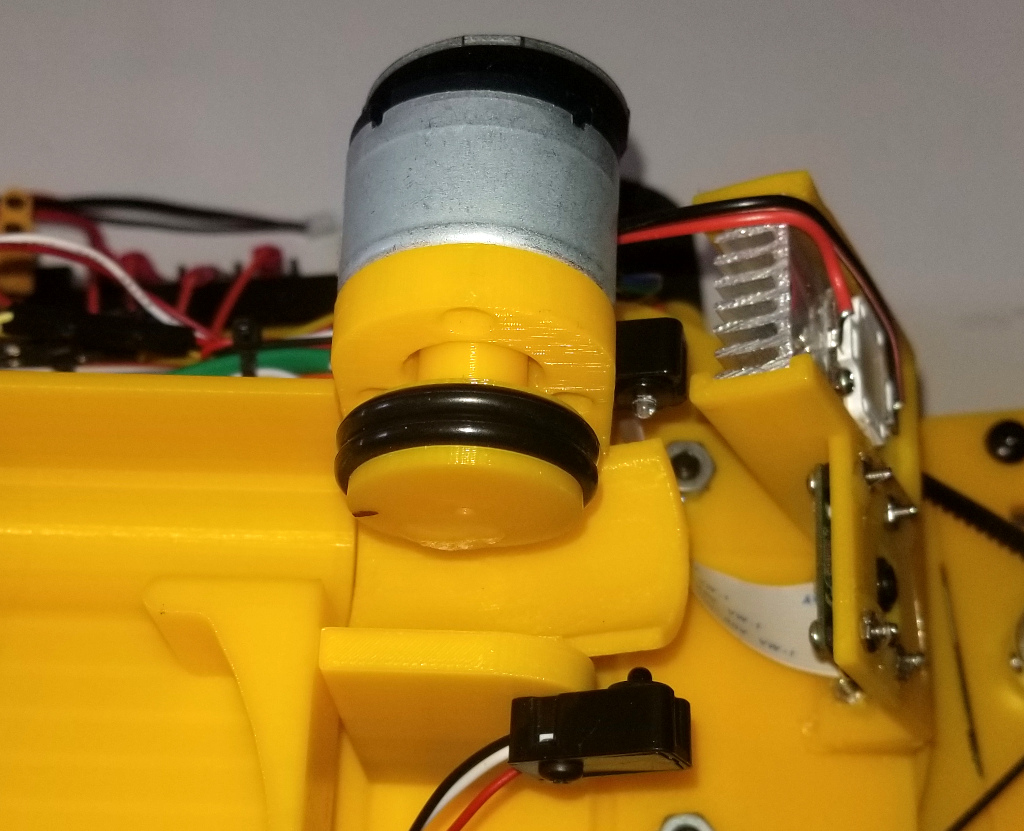
Now, attach the Flywheel to the Shooter Motor with a press fit as shown. Note that depending on your 3D printer the fit may be too tight or too loose. If it is too tight, drill out the hole in the Flywheel using a 3mm drill bit. If it is too loose, put a drop of glue from a hot glue gun on the hole of the Flywheel and immediately press it into position. Using hot glue instead of super glue will make it possible to remove the Flywheel later if needed.
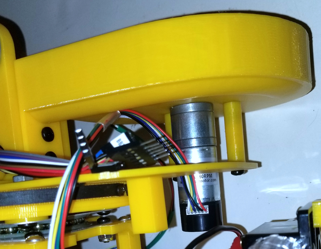
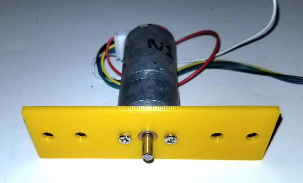
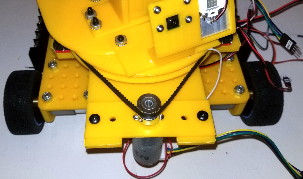
Now attach the Turntable Motor to the Turntable Motor Mount with two M3 screws as shown:
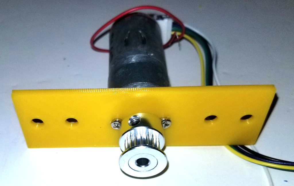
Then attach the Timing Belt Pully:
Finally, attach the Turret Motor Mount to the Chassis using two 8-32 bolts. Be sure to loop the timing belt around the Timing Belt Pully and adjust it so that the belt is taught but not tight. You should still be able to turn the turret an the belt should slip.
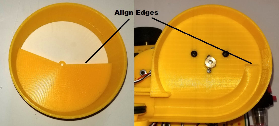
Finally attach the Ball Hopper to the Turret using tape. Be sure to align the two edges as shown below. Positioning the Hopper in other orientations can lead to a situation where the ball can jam when rotating the feeder in either direction making it impossible to unjam.