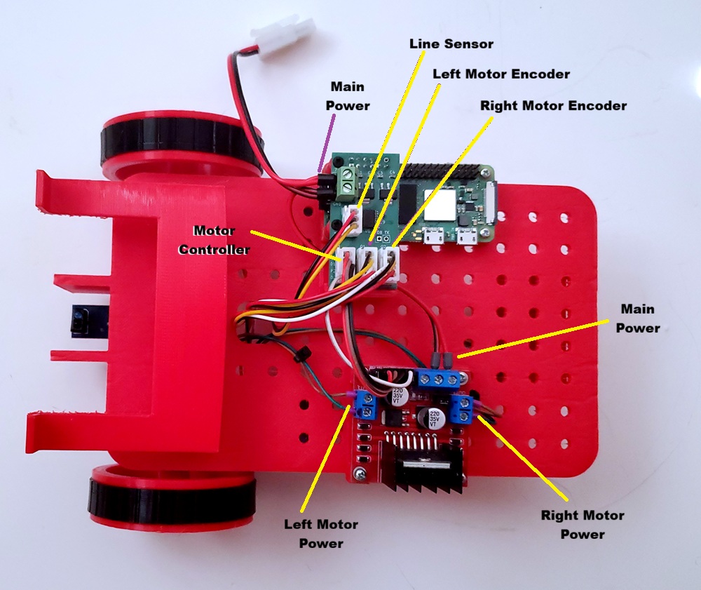
Wire the robot as shown:
Testing the Wiring
Launch VS Code and load the MinibotWiringTest project and run the program. If you need instructions on how to deploy and run your code on the Minibot, you can find them here.
Then in the Driver Station, connect and enable your program and press the B1 button. This should cause the robot to first drive the left wheel forward and then drive the right wheel forward. Verify that the correct wheels run in the correct direction at the appropriate times. If the wrong wheel runs, you have the left and right reversed. If the wheel runs in the wrong direction you have the power lines to the motor reversed.
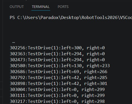
When the motors are running you will see the following output in the terminal window showing the speed for the left and right motors. While the left wheel is running the left speed should be non-zero and the right speed should be zero. When the right wheel is running it should be the opposite. If the speeds are reversed then you have the encoder connections reversed.
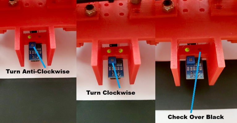
Now before we test the line sensor we need to calibrate it. Create a white sheet of paper with a black line as shown below. Then place the robot so the sensor is over the white and rotate the adjustment potentiometer anti-clockwise until the led on the right goes out as shown. Then slowly rotate the potentiometer right until the led goes back on as shown. Finally test the sensor by moving it over the black line and the light should go out.
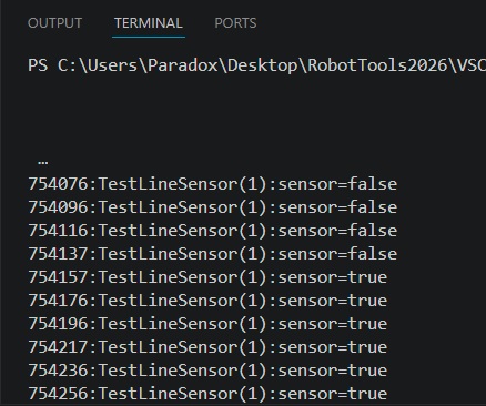
Now with the sensor calibrated, run the test program and press the B1 button. It should print out the state of the sensor as shown below. As you move it from the white to the black the sensor should change from false to true.
You robot should now be complete.