In this chapter we are going to cover assembling the Arduino Board. This will require soldering and the first thing you will need is a decent soldering iron. You will need one with a relatively small tip. You will also want one that controls the temperature of the tip by controlling the power delivered. I am fond of Weller soldering stations, but there are a number of other good choices.
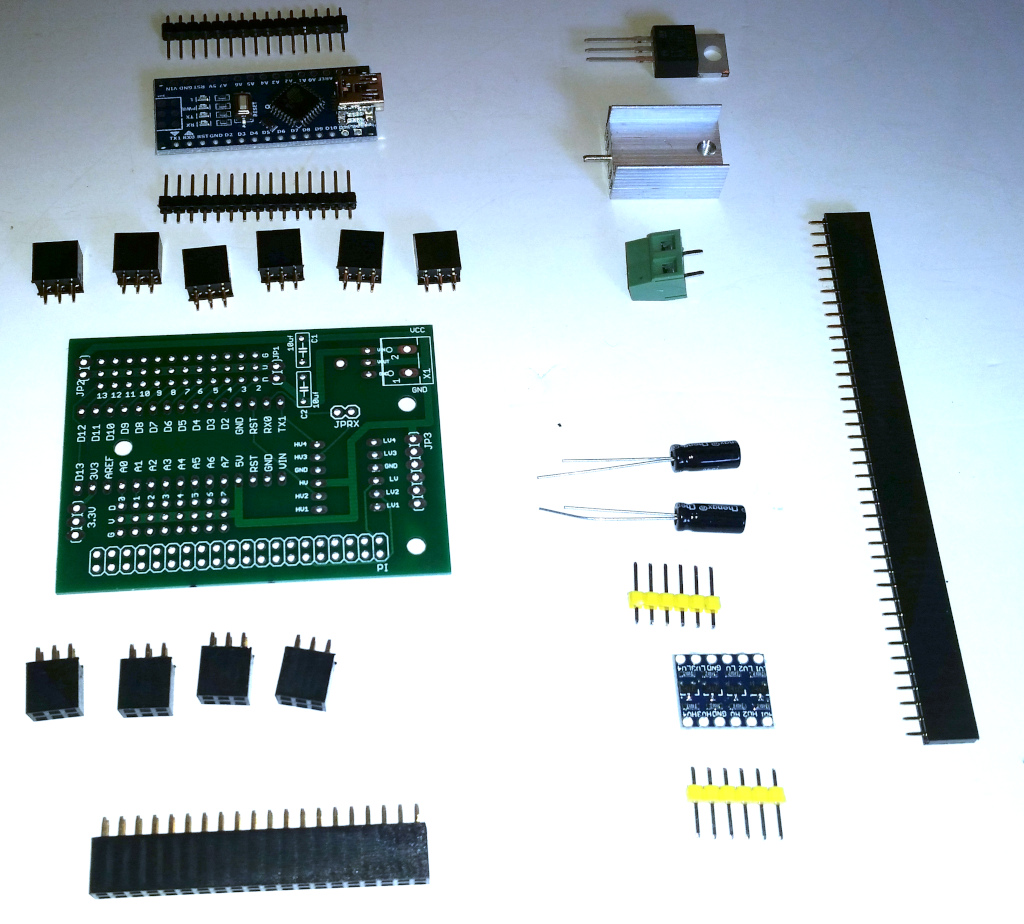
Lets start with the parts you are going to need:
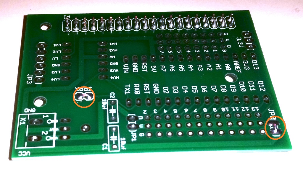
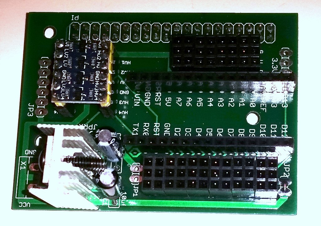
Before we start, let’s look at a couple of important features of the Arduino board:
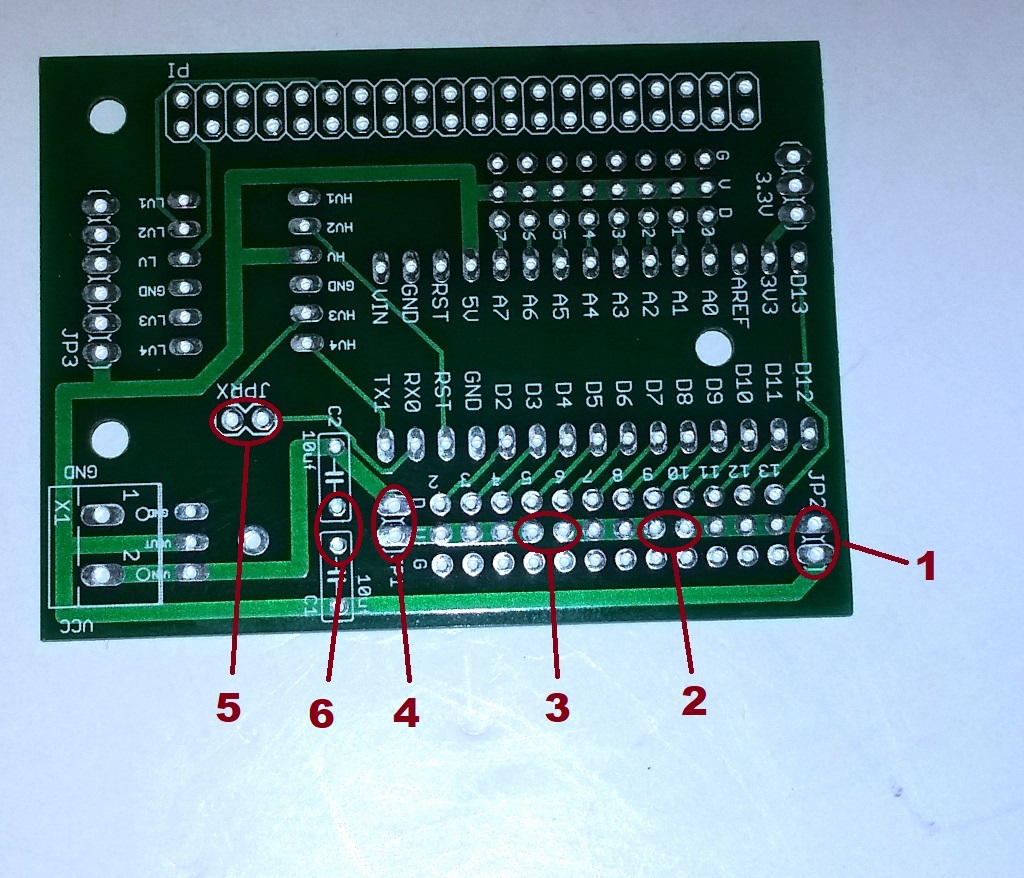
Referring to the above image note:
- Connecting this jumper will supply 5v to the middle port of pins 10, 11, 12, and 13.
- Connecting these two pins will connect the pin 10, 11, 12, and 13 voltage bus to pins 6, 7, 8 and 9.
- Connecting these two pins will connect the pin 2, 3, 4 and 5 voltage bus to pins 6, 7, 8 and 9.
- Connecting this jumper will supply the battery voltage to pins 2, 3, 4, and 5.
- You must connect this jumper to enable communication with the Pi.
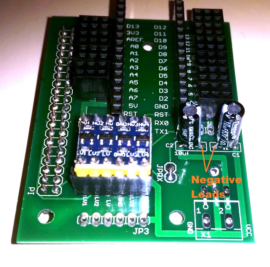
- When you attach the capacitors, the negative lead for each capacitor should attach here.
Some examples:
- If you want the center power line for all of the pins to be 5v, you would connect jumper marked as 1 and then connect the pins marked by 2 and 3. Do not connect the jumper marked as 4.
- If you want the center power line for all of the pins to be the battery voltage, you would connect jumper marked as 4 and then connect pins marked by 2 and 3. Do not connect the jumper marked as 1.
- You can, of course, have any combination of 5v and battery voltage by making the proper connections to 1, 2, 3, and 4. However, take care that you do not connect the 5v supply to the battery voltage.
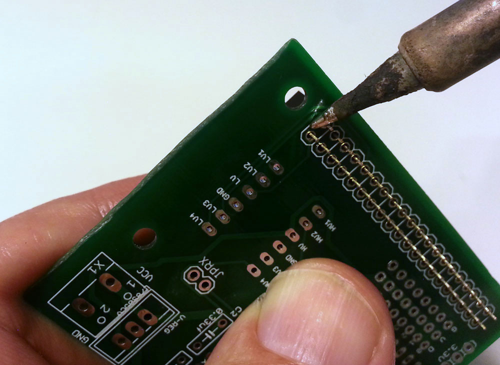
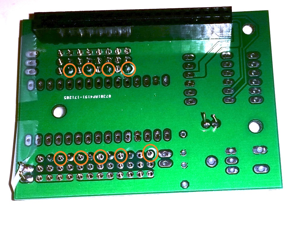
The first thing we are going to do is solder the 2×20 pin female connector that is used to connect the Arduino Board to the Raspberry Pi. Now this connector is soldered to the 2×20 hole array, but needs to be positions on the bottom of the board since this board will sit on top of the Rasberry Pi. Position the connector on the board as shown below and solder the one pin shown. It is important that you apply solder to that one pin only. Once you have soldered more than one pin of the connector it will be very difficult to adjust it’s position and we want to make sure that it is seated properly before we solder the rest of the pins.
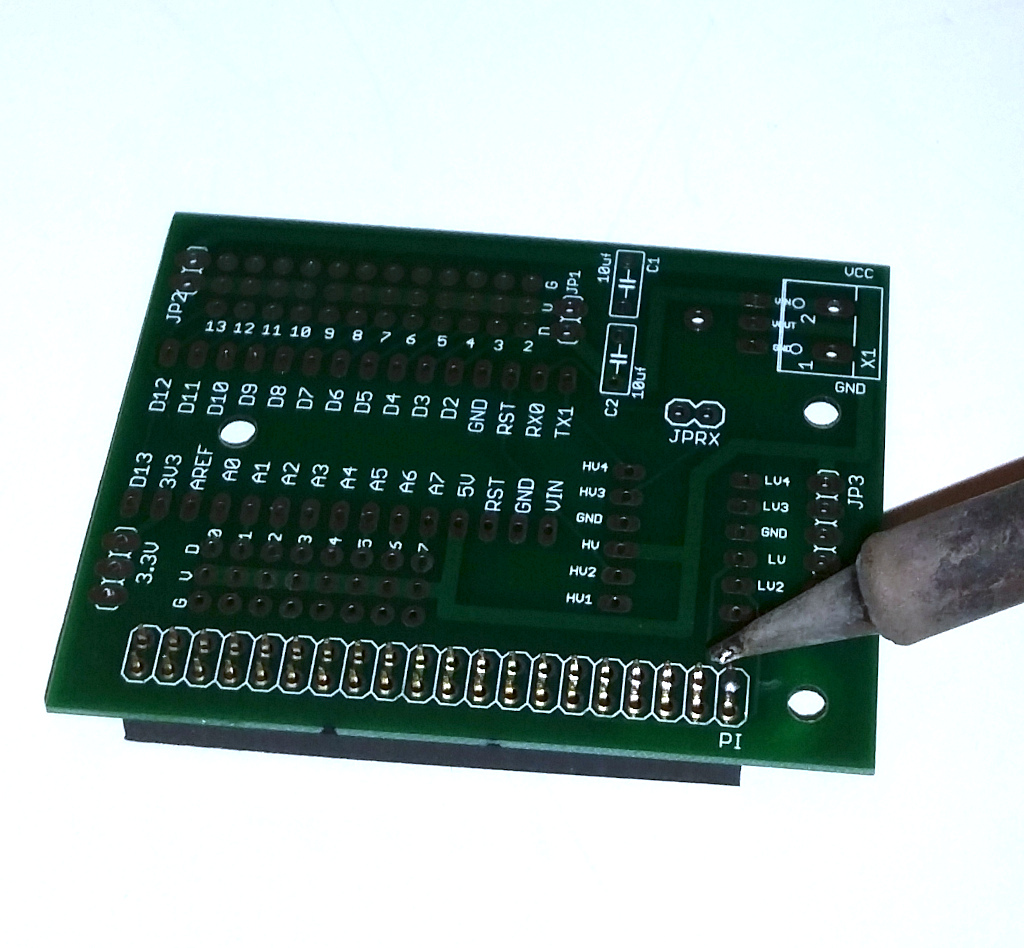
When making the solder connection, touch the soldering iron tip to both the pin sticking through the board and the pad to which you are soldering it. It is also important to heat the connection sufficiently so that the solder flows smoothly and does not clump up.
After you have soldered the first pin, pick up the board and you will probably find that the connector is crooked:
This is why we told you to solder only one pin. To fix this, pick up the board and put your finger on the connector. You can then heat the connection you just made to melt the solder which will allow you to re-position the connector as shown below:
Once you have the connector on straight, go ahead and solder the remaining 39 pins.
Next, using a short piece of solid wire, connect the two jumpers as shown below.
Now temporarily tape the 10 2×3 headers as shown below. This will hold them in place while we solder them.
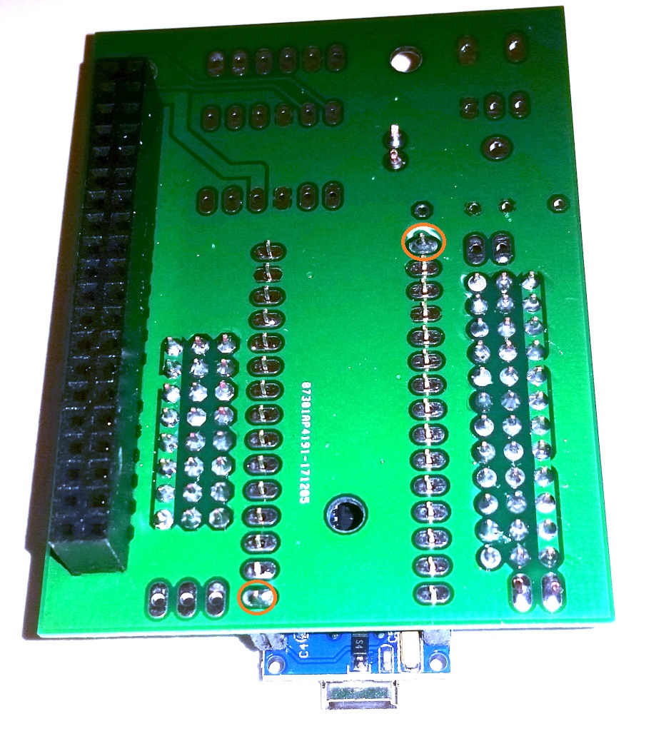
Now turn the board over and solder only a single pin on each of the 2×3 headers as shown below:
Now, while holding each of the 2×3 headers with your finger, heat its soldered pin and make sure that the header is seated. Once they are all seated, solder the remaining pins.
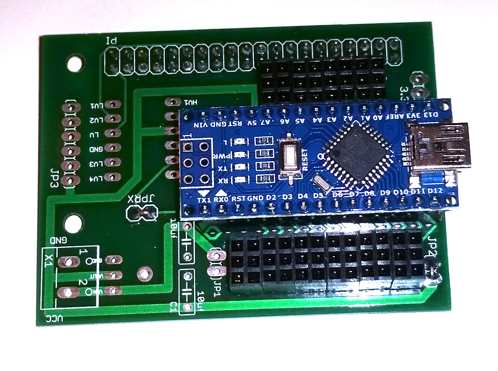
Next cut two 1×15 pieces of female header from your 1×40 piece of female header stock. The easiest way to cut this is to pull the 16th pin and then use a hacksaw to make a cut in the opening that is presented. Then insert the Arduinio’s two 1×15 male headers into the female headers you just cut and add the Arduino, but do not solder yet. After you have it assembled insert the whole assembly into the holes on the top of the PC board and turn it upside down. Then solder the two pins as shown below:
Once the two pins are soldered, make sure that the Arduino is seated properly and is not crocked and then solder the remaining pins on both the bottom and top.
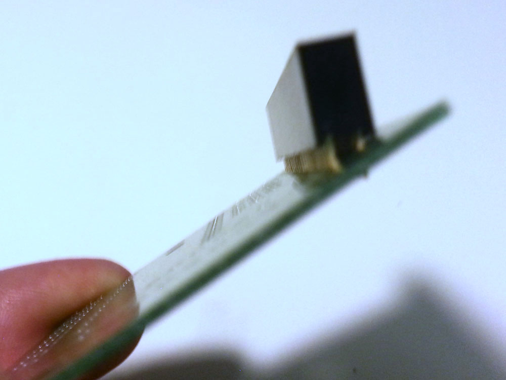
Now remove the Arduino. Then cut two 1×6 pieces of female headers and assemble them with the level shifter similar to what you did with the Arduino. Then insert the assembly into the top of the board and solder the two pins shown below:
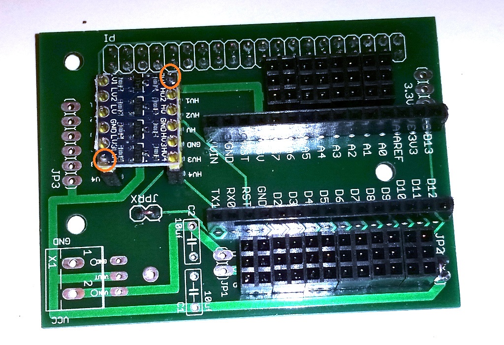
Now make sure that the level shifter is straight and seated properly and then solder the remaining pins on both the top and bottom.
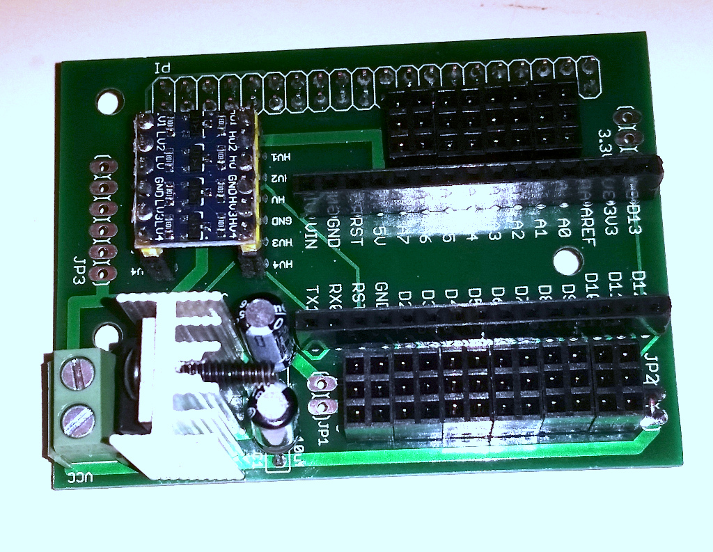
Next solder the two 10uf capacitors as shown below. Make sure that the negative leads are positioned properly:
Next attach the heat sink and voltage regulator and screw the voltage regulator into the heat sink. Then solder the 3 voltage regulator pins and the heat sink onto the board as shown:
Finally attach the screw terminal block and solder the two pins: