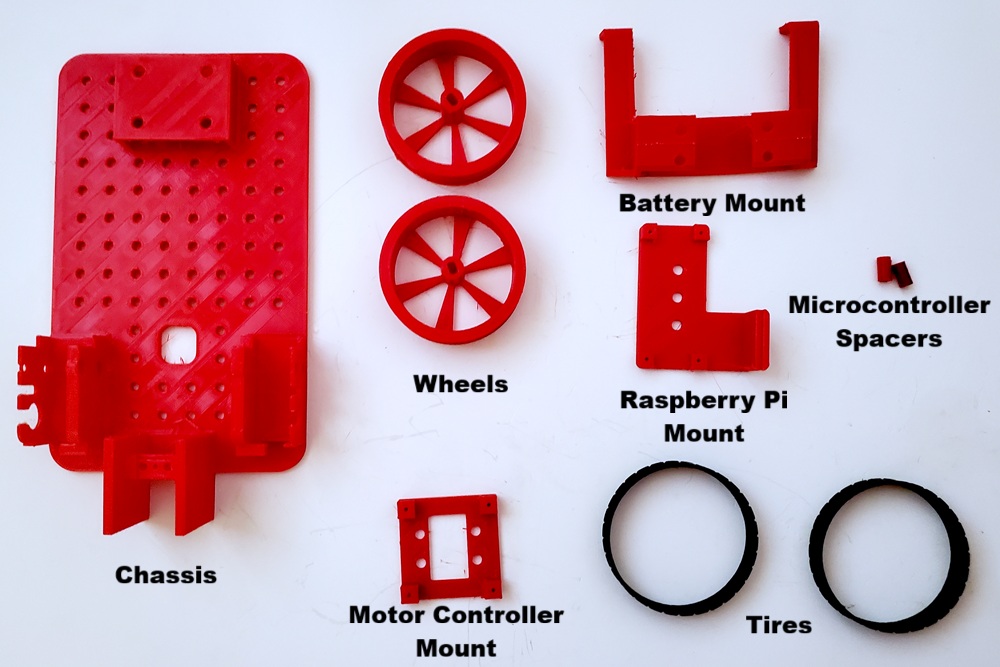
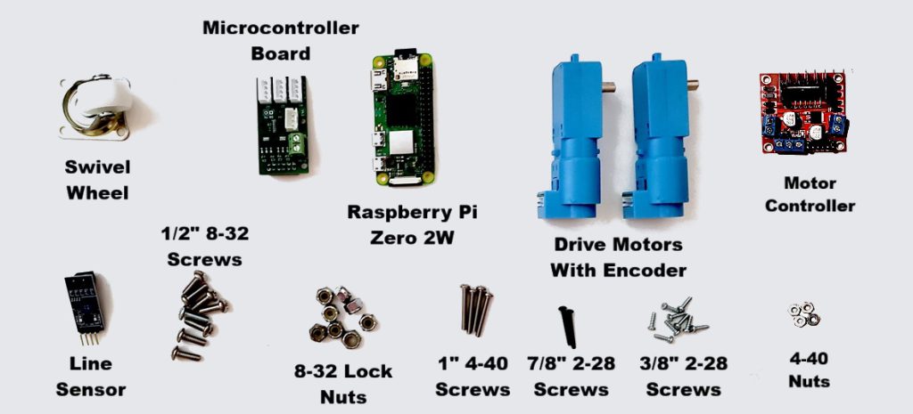
In this chapter we will list all of the parts required to build the robots used for the tutorials, including possible sources for those parts.
The brains of the robot will consist of a Raspberry Pi. Currently only the Raspberry Pi 3B/3B+ is supported but I hope to support the Pi 4 soon.
Raspberry Pi 3B+. You can get these at Amazon with free shipping (if you have Amazon Prime) for about $42. You will, of course, also need to add a micro SD card. |
The following set of parts are all 3D printed. You can download the STL files for these parts here.
The following is the set of miscellaneous ‘off the shelf’ parts with links to where you might find them. Note that the links below are mere suggestions and should not be seen an endorsement of that particular vendor.
Motor controller. This a L298N motor controller which uses PWM signals from the Arduino to control up to two motors at up to 2 amps. | |
IR Sensor. This is a TCRT5000 Infrared Sensor and is used to detect white and black lines. You will need two of these. | |
Swivel Wheel. This is used for the rear wheel of the robot. | |
Drive Motor. Two of these TT motors are needed for the drive wheels. Different gear ratios for these motors are available. The most common is 1:48, however I prefer the 1:120 version. The robot will move slower, but it will be more controllable. You can get these with or without the wheels. | |
Drive Wheel. You will need two of these to attach to the Drive Motors. You can purchase these separately from the motors, but you can also find them bundled with the motors. | |
20 cm, 40 pin Male/Female Dupont Cable. |
The next set of parts are needed for the Wheel Encoder board which provides the mechanism to measure the rotation and speed of the wheels
Encoder PC board. You will need two of these. This is a custom PC board. As discussed in the introduction, you can create the Wheel Encoder using a generic PC board and wiring it manually. However if you are going to want to make a number of these using a custom board like this is helpful. I do have a small number of these boards available and if there is enough interest, I can get more made. Contact me at robotics@gabysoft.com if you are interested. | |
1×4 Right Angle Male Header. You will need two of these, one for each encoder. | |
150K ohm pullup resistor. You will need four of these, two for each encoder. | |
Contineous rotation potentiometer. You will need four of these, two for each encoder. |
The next set of parts are needed for the Arduino board which controls the motors and sensors and communicates with the Raspberry Pi via the serial port.
Arduino PC board. This is a custom PC board. As discussed in the introduction, you can create the Arduino Board using a generic PC board and wiring it manually. However if you are going to want to make a number of these using a custom board like this is helpful. I do have a small number of these boards available and if there is enough interest, I can get more made. Contact me at robotics@gabysoft.com if you are interested. | |
Arduino Nano. This microcontroller is used to control the motors and sensors. |
|
LD1085V50 Voltage Regulator. This converts the battery voltage (~8v) to the 5.0v needed by both the Raspberry Pi and the Arduino. It is capable of delivering a total of 3 amps. | |
Heat Sink. This attaches to the Voltage Regulator to provide cooling. | |
Bi-Directional Level Shifter. The Raspberry Pi uses 3.3v logic signals and the Arduino uses 5v logic signals. This module converts between the two. | |
2×3 Female Header. You will need 10 of these. | |
10 uf Ceramic Capacitor. You will need 2 of these. | |
1×40 Female Header. You will need two of these. |
|
2×20 Female Header. |
|
2 Pin 5mm Screw Terminal Block. |
You will also need a battery to power your robot.
7.2 NiMh Battery. You can also use a 2s LiPo battery if you prefer, but the NiMh battery is safer and you don’t have to worry about discharging it too far. |
You will also need a variety of screws and bolts.