We will now wire the Chassis.
Analog Encoders
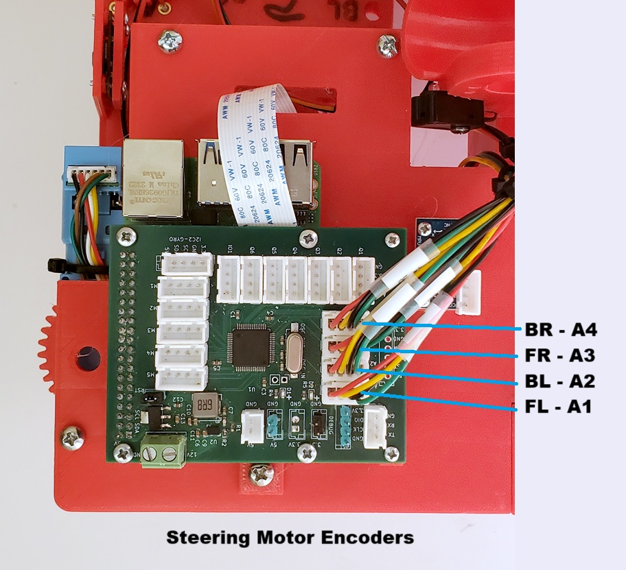
First connect the four Steering Motor Encoder cables to the Microcontroller as shown:
Quadrature Encoder
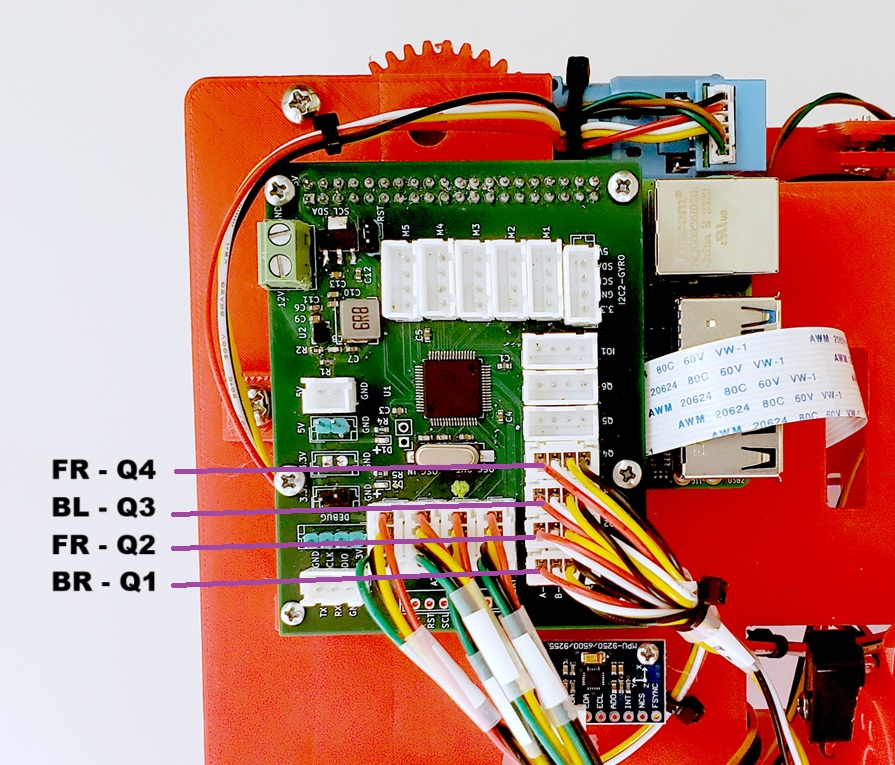
Next connect the four Drive Motor Encoder cables to the Microcontroller as shown:
Drive / Steering Motor Controllers
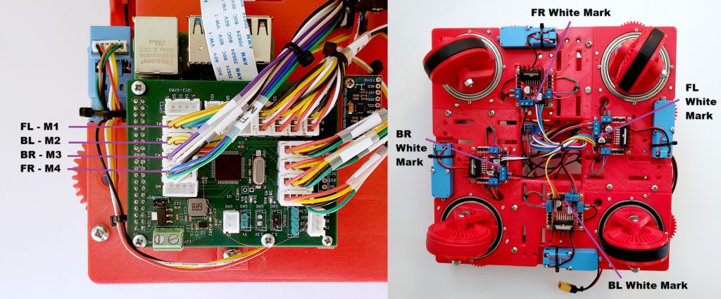
Then connect the Motor Controllers for the Drive and Steering motors as shown:
Pay close attention to the position of the White Mark you placed on the Motor Controller Cables. Orient them as shown above.
Motor Controller Power
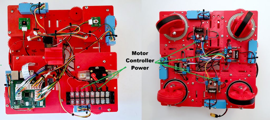
Now connect the power to the Motor Controllers as shown below.
Make sure that you connect the polarity correctly. Connecting the power up backwards would be very bad.
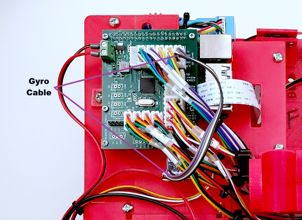
Gyro
Now use the Gyro Cable to connect the Gyro to the Microcontroller as shown:
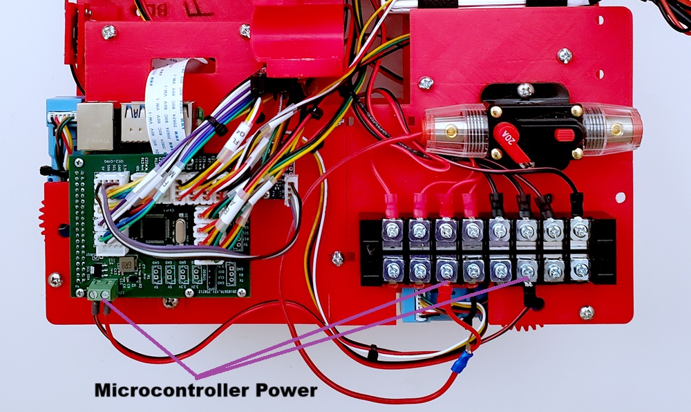
Microcontroller / Raspberry Pi Power
Then connect the power to the Microcontroller / Raspberry Pi as shown.
Again, make sure that you have the correct polarity.
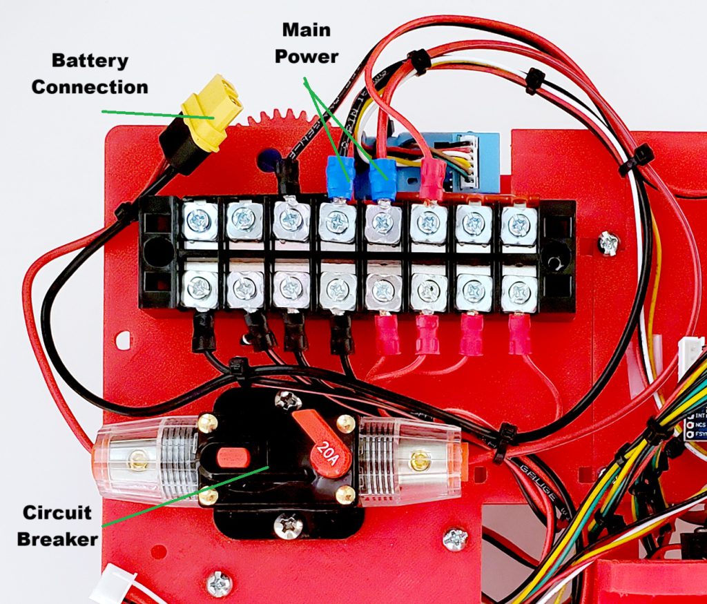
Main Power
Finally, connect the Main Power through the Circuit Breaker as shown.
Once again, make sure you have the polarity correct or very bad things will happen.
You can Test The Wiring for the chassis now, or you can wait and do all of the testing once the shooter is complete.
