We will now perform a series of tests to make sure we have wired the robot correctly.
First you need to load and run the SwerveBotWiringTest project that you can find in the VSCode folder of RobotTools2024.
If you are unfamiliar with how to run programs on the robot, refer to this section of the Minibot Tutorial.
Swerve Motor Testing
To test the Steering Motors either prop the robot off it’s wheels or turn it upside down. Then run the SwerveBotWiringTest project and the press the B1 button from the Driver Station (don’t forget to Connect and Enable first). When you do this the four Steering Motors should run in sequence in the order Front Left, Back Left, Back Right and Front Right. You should ensure that each motor runs a the correct time. If the run out of order then you need to check the motor connections to the Microcontrollers.
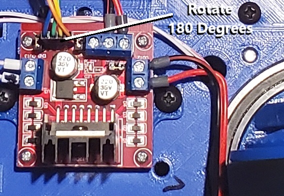
If the Drive motor runs instead of the Steering motor this means that you have the connection to the Motor Controller reversed and you need to switch it as shown:
Then check that all of the wheels are turning counter clockwise when viewed from the top (clockwise when viewed from the bottom). If any motor is turning the wrong direction it means that you have the power connection to the motor controller reversed. You can fix it by switching the power connection as shown below (preferred), or if you like you can fix it in software by calling the setInverted function for that motor.

Finally you need to make sure that all of the Steering Encoders are working. When the command runs the position for all of the Steering Encoders will be printed into the Terminal Window. Make sure that the encoder that changes corresponds to the current motor running. If it is wrong then you need to check the encoder connections to the Microcontrollers. Also, when the motor runs these numbers should always be increasing. The easiest way to see this is to copy the data and paste it into your favorite spreadsheet and graph it. When I do this for my robot I get the following graph:
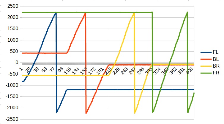
Note here that the all of the graphs have a positive slope and that the Front Left moves first followed by the Back Left, Back Right and Front Right. There should be no way that the slopes are negative unless you somehow installed the encoder upside down.
Drive Motor Testing
Once again either prop up the robot or turn it upside down. Then run the SwerveBotWiringTest project and run the Drive Motor Test by clicking the B2 button (after connecting and enabling of course). As with the Swerve Motor Test each of the four motors will run one at a time in the order, Front Left, Back Left, Back Right and Front Right.
You should make sure that the correct motor runs at the correct time. If this is not the case then you should check your Drive Motor connections on the Microcontrollers. Note that since the Swerve and Drive motors are connected to the same Motor Controller if you fixed this for the Swerve Motors this should work for the Drive Motors.
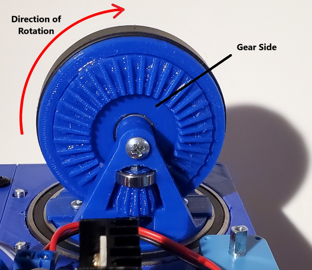
Also make sure that the wheel is rotating in a clockwise direction when view for the side with the gear as shown below:
If the motor rotates the wrong direction you can either swap the power connection on the Motor Controller as described above (preferred) or use the setInverted function for the motor.
Finally you need to make sure that the encoders connected correctly and are counting the correct direction. The speed of each of the wheels is printed out in the Terminal window. Once again you can plot the data and you should get something like:
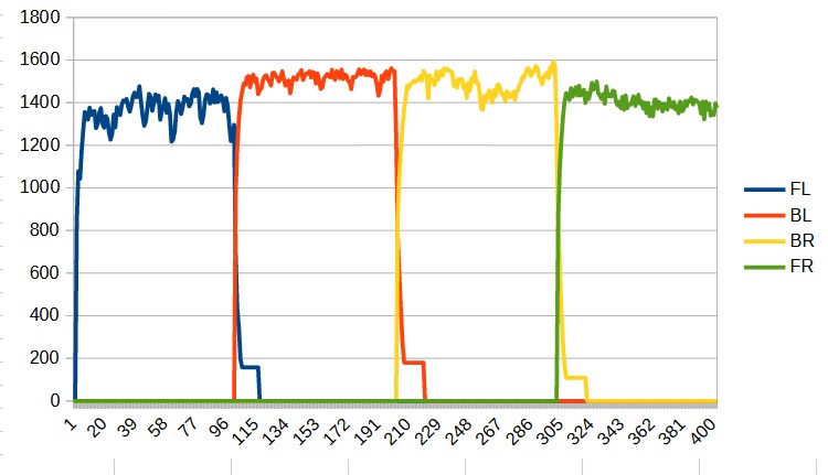
First make sure that the encoders are associated with the correct wheel. Here we can see that the Front Left motor runs followed by the Back Left, Back Right and Front Right. If the wrong encoder is being used for any of the motors you must have the Encoder connection on the Microcontrollers incorrect.
Finally the speed for all of the wheels should be positive. If the wheel is rotating the correct direction but the speed is showing negative them you connected the A/B connections reversed when you make the connecting cable. To fix this you can reverse the connections on the connector but it is actually quite difficult (but not impossible) to remove the connectors once they have been inserted into the housing. The other alternative is to use the setInverted function for the encoder. If you go this route you will need to remember the this will need to be done by every student working through the tutorial.
Feeder Testing
To test the Feeder Motor, press the B3 button on the Driver Station which should toggle the Feeder Motor in the forward direction.
If it runs the wrong way, either swap the feeder power connection on the Motor Controller or use the setInverted function on the motor. Also the speed of the feeder motor will be printed to the Terminal Window. Make sure that this value is not zero. The sign for this encoder is not important as we will only be using it’s magnitude to detect whether the feeder has stalled as a result of a ball jam.
Shooter Testing
To test the Shooter Motor, press the B4 button on the Driver Station which should toggle the Shooter Motor in the forward (counter clockwise when viewed from the side). Again if the motor runs backwards either swap the power connection or use setInverted.
The speed is printed to the Terminal Window. Make sure that the speed is positive. If it is negative (and the Shooter is running the correct direction) you will either need to swap the A/B lines on the encoder connector (hard) or use the setInverted on the Encoder.
Ball Counter Testing
To test the Ball Counter, press the B5 button on the Driver Station. While this is active, the ball count will be printed to the Terminal Window. Use your finger to break the beam and see if the counter increments. Remember that the counter counts both when the beam is broken and when it is resorted so you will get a count of two each time you break the beam. If the counter is not working check the wiring for both the Sensor and the LED.
Gyro Testing
To test the Gyro, press the B6 button. This should then print the current gyro heading to the console. You can rotate the robot by hand to see if the gyro is giving the correct readings.
Camera Testing
To test the Camera Connection, bring up a command prompt and type
ssh pi@10.21.2.2
to open a secure shell to the Raspberry Pi. The password is raspberry. Then enter
./runcamera
to start the camera server. If the camera is working you will see something like this
|
1 2 3 4 5 6 7 8 9 10 11 12 13 14 15 16 17 18 19 20 21 22 23 |
[0:03:04.828733407] [819] INFO RPI vc4.cpp:444 Registered camera /base/soc/i2c0mux/i2c@1/ov5647@36 to Unicam device /dev/media4 and ISP device /dev/media1 - ov5647 1 Streams: 0: width=800, height=600 [0:03:04.829350253] [813] INFO Camera camera.cpp:1183 configuring streams: (0) 640x480-RGB888 [0:03:04.829745818] [819] INFO RPI vc4.cpp:608 Sensor: /base/soc/i2c0mux/i2c@1/ov5647@36 - Selected sensor format: 640x480-SGBRG10_1X10 - Selected unicam format: 640x480-pGAA Width=640,Height=480,Stride=1920 Default viewfinder configuration is: 640x480-RGB888 Validated viewfinder configuration is: 640x480-RGB888 [0:03:04.831106483] [813] INFO Camera camera.cpp:1183 configuring streams: (0) 640x480-RGB888 [0:03:04.833013222] [819] INFO RPI vc4.cpp:608 Sensor: /base/soc/i2c0mux/i2c@1/ov5647@36 - Selected sensor format: 640x480-SGBRG10_1X10 - Selected unicam format: 640x480-pGAA StartCapture Normal Settings ProcessStart dec=4.000000,sig=1.000000,nth=4,refe=1 0: FPS = 29.72, GPS = 490703133.33, proc = 100, grabbed = 1651076242, dt=3.364715 ImageProcessingServer started ImageServer started Waiting for processing connection 0: FPS = 31.77, GPS = 31.77, proc = 100, grabbed = 100, dt=3.147718 0: FPS = 31.86, GPS = 31.86, proc = 100, grabbed = 100, dt=3.138413 Waiting for image connection 0: FPS = 31.86, GPS = 31.86, proc = 100, grabbed = 100, dt=3.138721 |
If the camera initialization fails, you will see something like:
|
1 2 3 4 5 6 7 8 9 10 11 12 13 14 15 16 17 18 19 20 21 22 23 24 25 |
Lens for camera 0: Pi Camera 640x480 Shutter Speed = 20, Exposure = 0, Frame Rate = 50 newShutterSpeed=20 Shutterspeed = 20 newExposure=0.000000 Exposure = 0 newFrameRate=30 Frame rate = 30 whiteCnt = 3 MinSize = 20 WhiteDrop = 80 MinBlack = 16 MaxSlope = 0.300000 MaxParallel = 0.150000 MaxAspect = 1.300000 MaxAspect = 0.700000 newBrightness=0 Decimate = 4.000000 newContrast=100 contrast=100 StartCapture [0:00:55.460738689] [931] INFO Camera camera_manager.cpp:284 libcamera v0.1.0+118-563cd78e [0:00:55.483170392] [931] INFO Camera camera_manager.cpp:284 libcamera v0.1.0+118-563cd78e No cameras were identified on the system. Cannot initialize camera |
In that case you need to check your camera cable connection.
Congratulations your robot is now ready for use!