This chapter will go over 3d printing the parts needed for the SwerveBot. The STL files can be found here.
Printing the swerve modules is a bit tricky as they require dimensionally accurate prints. If the gears are slightly too large, they will not run smoothly and if they are slightly too small they will slip. Before you begin, you need to look up the instructions on how to calibrate the X, Y, Z and Feed for your specific printer. This will give you the best chance for success.
For most of the parts I use a 20% fill and 2 walls. The layer height is either 0.2mm or 0.3mm and the folder names indicate which. Some parts require a different fill and/or wall count and that will be reflected in the name and you should respect that. Also some parts require support which is also reflected in the folder names. I recommend Tree supports. If the file name has a number in parenthesis (e.g. part(3).stl) it means that you will need that number of copies. Note that if the part is in the SwerveModule folder, this is the number needed for a single swerve module. All of the parts should be printed in their current orientation.
I now going to list groups of parts and what settings I use to print them.
Swerve Module Parts
Before you start printing the parts for the Swerve Module, you may want to print the SwerveBaseTestPrint.stl file. This should be printed with a 0.3 mm layer height. It is a small part (compared to the full base) into which you should be able to place the large bearing. The bearing should fit snuggly. If it is too loose you may want to scale your models down slightly. If it is too tight you may want to scale your models up slightly.
The following are the parts that needed for a single Swerve Module. You will need to build four Swerve Modules.
Layer height 0.3mm, no support
I print the following set of parts using a 0.3mm layer height and no support.
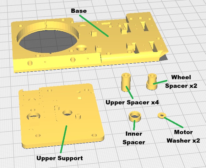
There are two versions of the Base and Upper Support, one for imbedded nuts and the other for heated brass inserts. The version of the Base for inserts has text on the bottom indicating where the inserts should be placed for each of the four positions (i.e. Front Left, Back Left, Back Right and Front Right). This will allow you to place inserts only in the needed positions for that particular position. To get the text to print properly you may want to print the first layer at a reduced speed.
When printing with imbedded nuts, I have found that it is really too much trouble to try and put nuts in based on the particular position of the piece so I always fill all of the nuts for every print. This makes all of the prints interchangeable.
Inserts vs Imbedded nuts
When we need to attach screws we can either use threaded inserts which are inserted into the parts after printing using heat or we can imbed nuts into the parts when they are printed. The advantage of embedding the nuts is that you do not need to add the inserts after printing. The disadvantage is that you must pause the print to insert the nuts.
I personally prefer using imbedded nuts.
Printing the ones with inserts is straightforward. However to print the versions with embedded nuts, you will need to create your G-Code files with commands to pause the print so that you can insert the nuts. I am using UltiMaker Cura for my slicer and the following is the procedure to create the G-Code file for the Upper Support. If you use a different slicer, you will have to figure out how to do it, but it will probably be fairly similar to this.
First import the piece and slice it using a 0.3mm layer height. Then use the tool that allows you to see the layers and move it down until you find the top of the nuts.
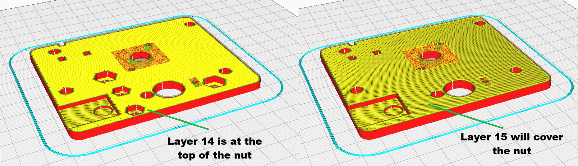
Here we can see layer 14 is the top of the nut because layer 15 covers it. This means that we need to pause the print at layer 14.
To do this, choose Modify G-Code option for the Extensions menu:
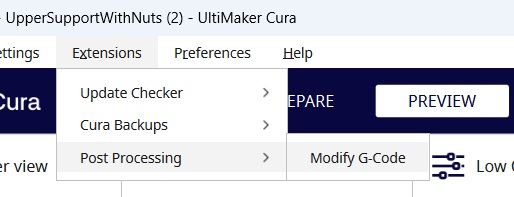
Then choose the Pause at height option:
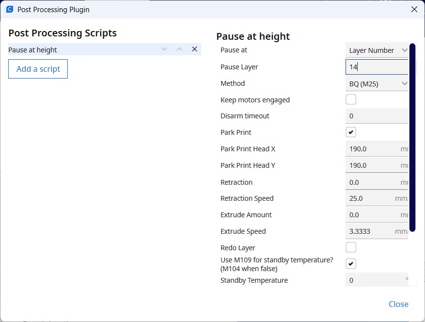
Then set the Pause Layer to 14. Also you will need to choose the correct Method for your printer. My printer needs to use the M25 G-Code command to properly pause the printer.
The Base also has nuts so will require a pause. Note that the pause point might be different so you should determine them in the same way as for the Upper Support.
As a final note, if you are printing the versions with the nuts, after printing you need to drive a screw through the nut to break the support layer which slightly blocks the hole.
Layer height 0.2mm, no support
The following parts should be printed using a 0.2mm layer height. If you print them in the orientation shown below, you will not need supports.
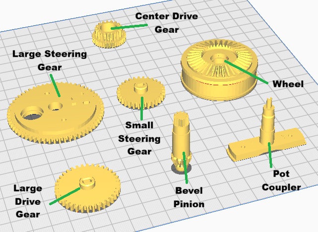
There are two versions of the Large Steering Gear one requiring inserts and the other embedded nuts.
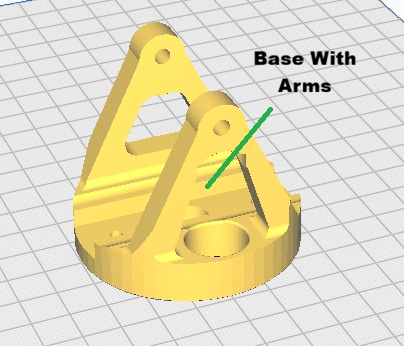
Layer height 0.2mm, support required
The following part needs generated support. I recommend using Tree Supports, but your milage might vary.
Robot Parts
This section specify how to print the remaining parts for the robot.
Layer height 0.3mm, no support
The parts shown below should be printed using 0.3mm layer height with no support:
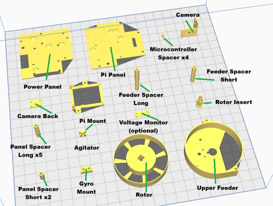
The pi panel come in two versions, one with embedded nuts and one that requires inserts. There are four versions of the Power Panel. I initially used LiPo Batteries and the panel for these has a spot to attach a voltage monitor to make sure the battery is not discharged too far (which will ruin it). Lately I have been using NiMh batteries which don’t have this issue (as well as being safer). These batteries are taller and required me to shorten one side of the panel to get them to fit which eliminated the space for the monitor. Both the LiPo and NiMh panels also have a version for embedded nuts and inserts.
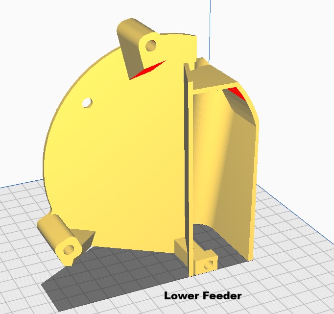
Note that the Upper Feeder will require 3 inserts after printing. Because of the thinness of the bottom inserted nuts were not possible.
Finally, there is a Voltage Monitor Mount part. The NiMh batteries do not require a voltage monitor but having an optional voltage display is useful.
Layer height 0.2mm no support
The parts shown below should be printed with a 0.2mm layer height with no support.
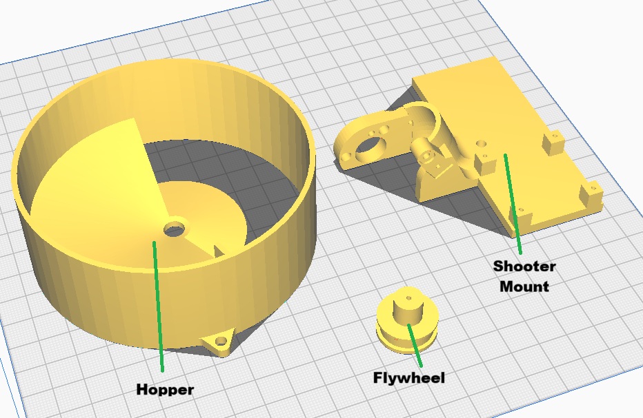
The Shooter Mount requires either inserts or embedded nuts. The Flywheel should be printed with 100% fill for maximum moment of inertia.
Layer height 0.2mm, with support.
The following should be printed with a 0.2mm layer height with support. I recommend “Tree” supports. Note that this part requires inserts. Because of the printing orientation, using embedded nuts is not possible.