Parts
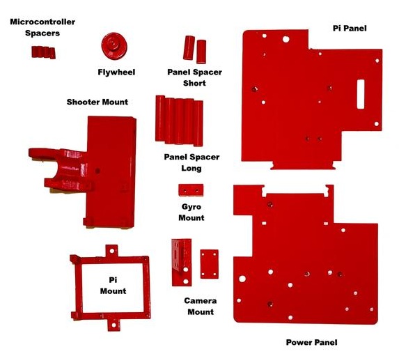
In addition to the four Swerve Modules you built in the previous chapter you will need the following 3D printed parts:
Plus the following hardware and electronics:
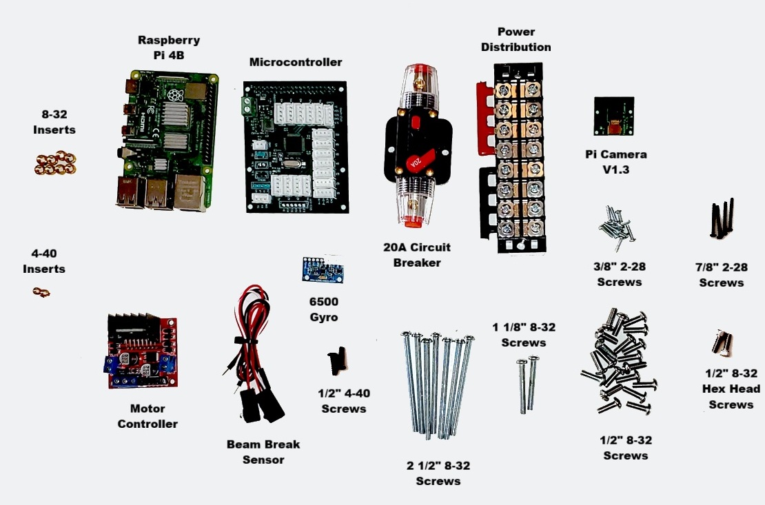
Note that if you chose to print the parts with the imbedded nuts, you will not need the inserts.
Assembling the Swerve Modules
First attach the two of the Swerve Modules together using two 1/2″ 8-32 Screws as shown:
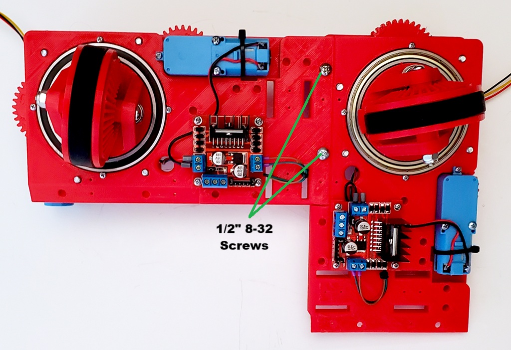
Then in a similar manner attach the Front Right and Back Right modules using six more 1/2″ 8-32 Screws as shown. Since each of the modules has a unique set of nuts/inserts, make sure you arrange them properly. You can tell which is which by locating the specific screws indicated in the image to the left.
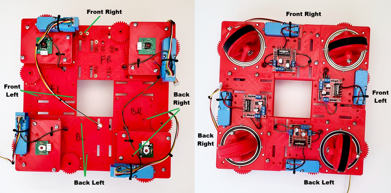
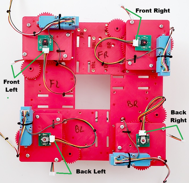
Finally connect the four Absolute Encoder cables into each of the four Encoders as show. Make sure that the labels on the cables match the Swerve Module.
Add Screw Inserts To Panels and Shooter
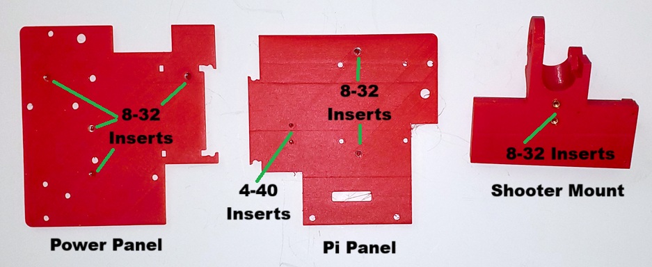
If you chose to print the versions that use inserts you will now need to screw inserts into the two Panels and Shooter Mount as shown below:
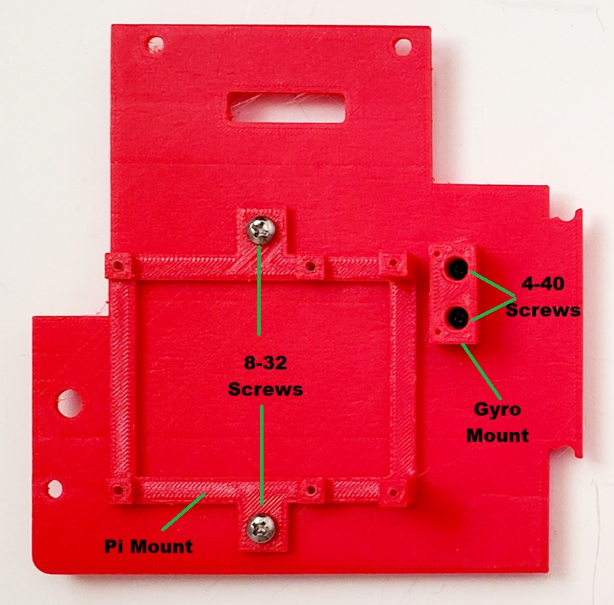
Next mount the Raspberry Pi Mount to the Pi Panel with two 1/2″ 8-32 Screws and attach the Gyro Mount to the Pi Panel with two 1/2″ 4-40 Screws as shown:
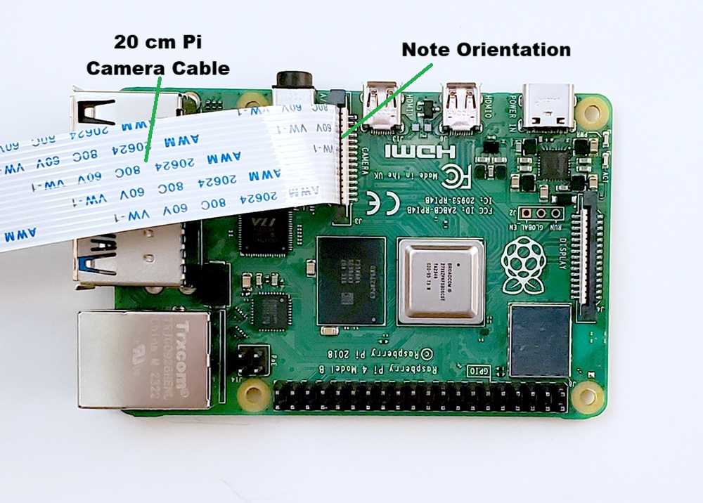
Now attach the 20 cm Pi Camera Cable to the Raspberry Pi 4B as shown. Pay attention to the orientation of the cable:
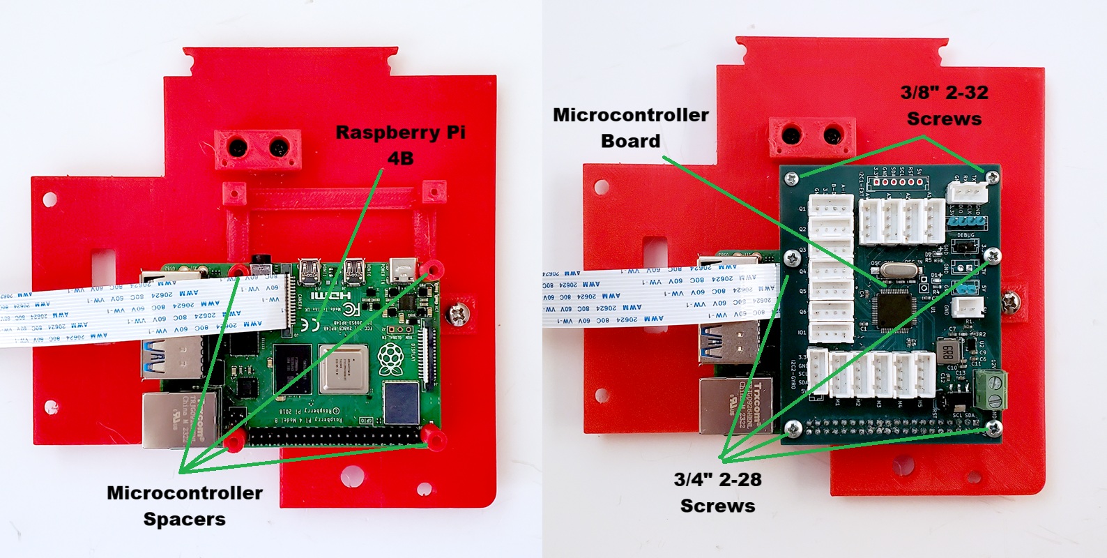
Then attach the Raspberry Pi and the Microcontroller Board to the Pi Mount as shown:
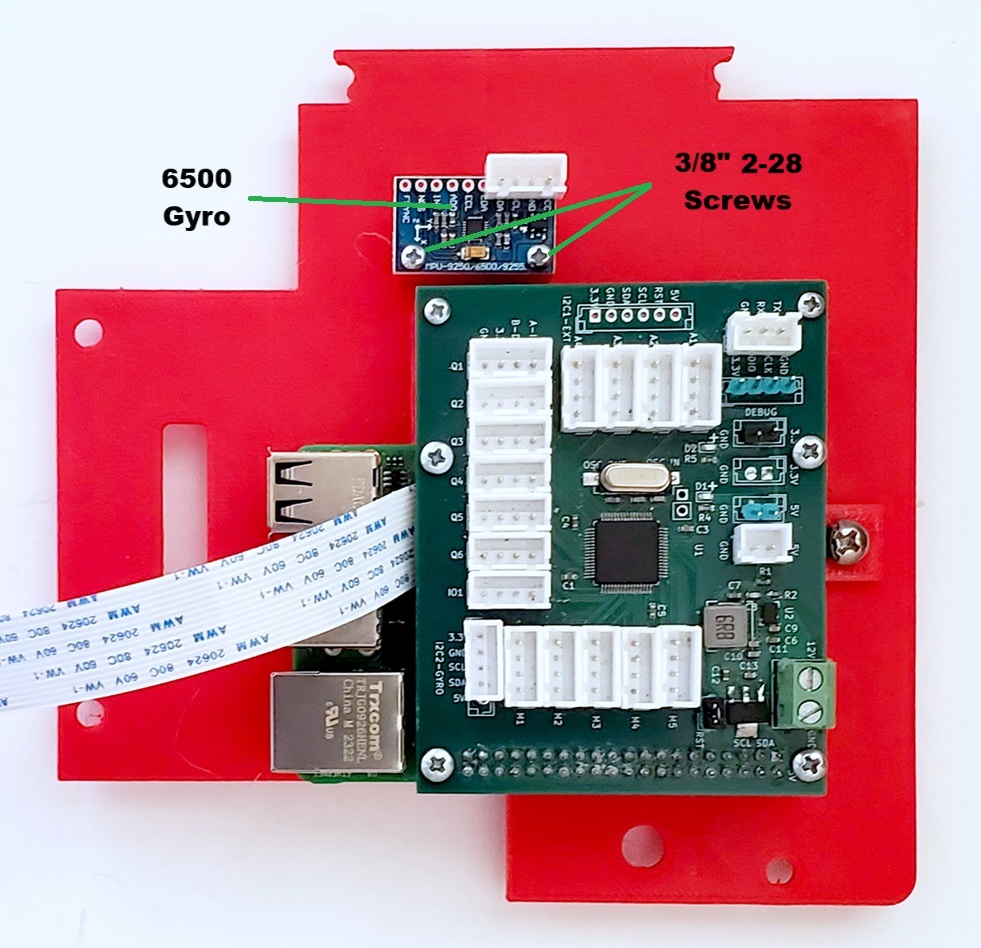
Now attach the Gyro to the Gyro Mount using two 3/8″ 2-28 Screws as shown:
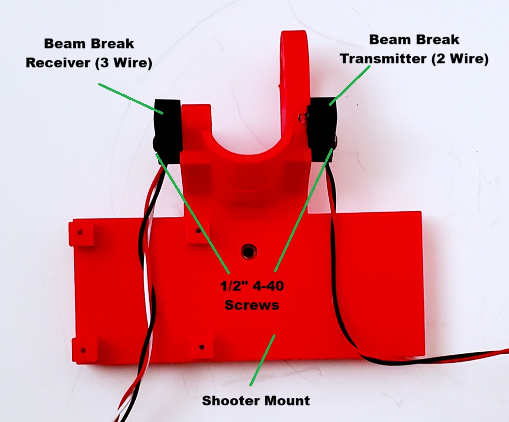
Next attach the Beam Break Sensors to the Shooter Mount as shown:
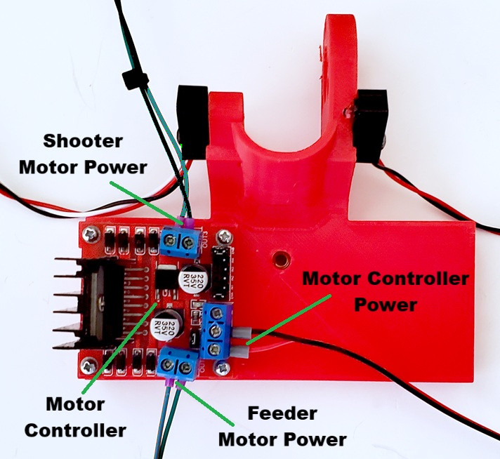
Then attach the Motor Controller to the Shooter Mount. At this point also connect the power for the Feeder Motor, Shooter Motor and Motor Controller as shown. We connect the power now because, once mounted, the Motor Controller will be less accessible.
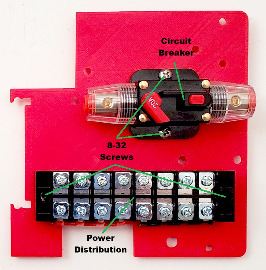
Now attach the Power Distribution Module and the Circuit Breaker to the Power Panel using four 1/2″ 8-32 Screws as shown:
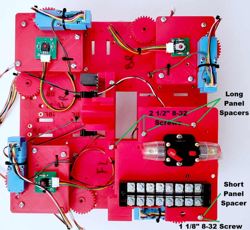
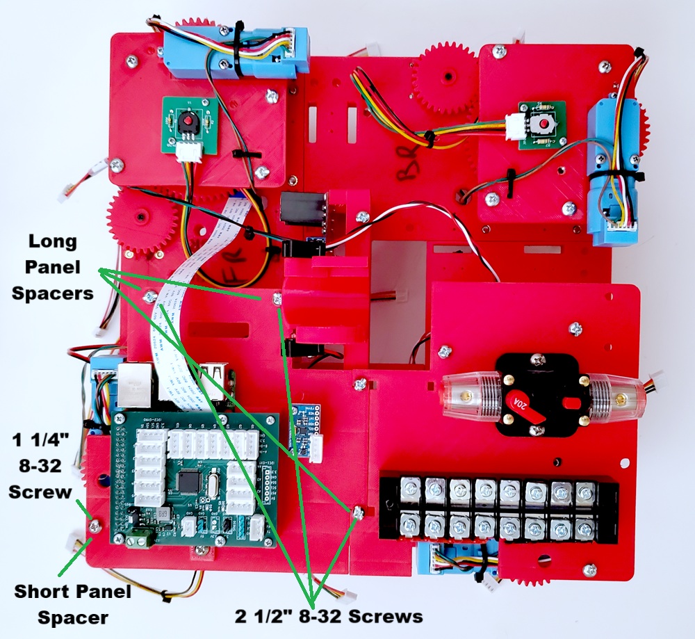
It is now time to assemble the remainder of the Chassis. For this you will need six 2 1/2″ 8-32 Screws, two 1 1/8″ 8-32 Screws, six Long Panel Spacers and two Short Panel Spacers.
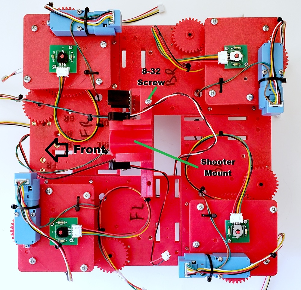
First attach the Shooter Mount to the Chassis as shown. Note that you should use only a single 8-32 screw for now:
Now attach the Power Panel using three 2 1/2″ 8-32 Screws with two Long Panel Spacers and a 1 1/8″ Screw with a Short Panel Spacer as shown. Do not tighten the indicated screw yet.
Now attach the Pi Panel using three 2 1/2″ 8-32 Screws with three Long Panel Spacers and one 1 1/8″ 8-32 Screw with a Short Panel Spacer as shown. You can now tighten all of the screws.
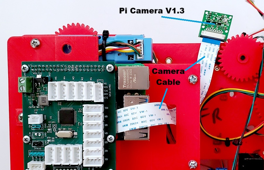
Next, run the Camera Cable through the slot in the Pi Panel and connect it to the Raspberry Pi Camera V1.3 as shown. Pay attention to it’s orientation.
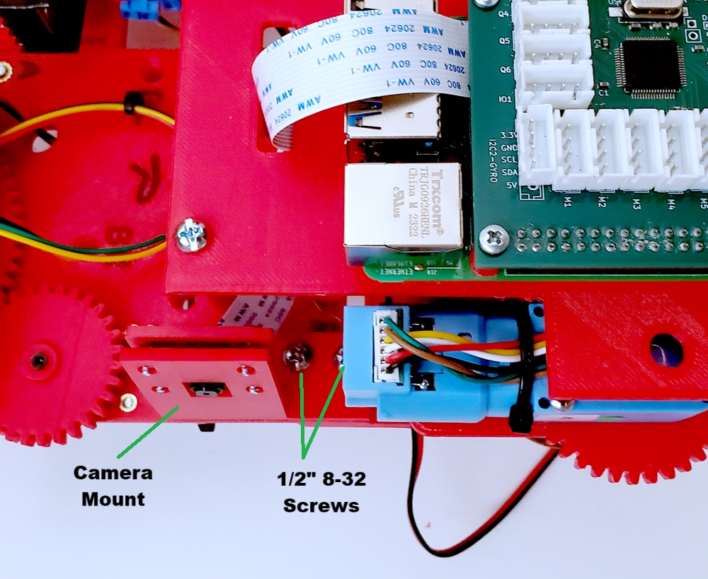
Then mount the Camera onto the Camera Mount using four 3/8″ 2-28 Screws as shown:
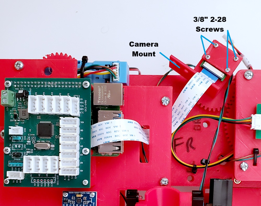
Finally, mount the Camera Mount to the Chassis using two 1/2″ 8-32 Screws as shown. Make sure that the camera is parallel to the front of the robot.