The drive subsystem for a swerve drive robot is considerably more complex than that of the simple tank drive that you created for the Minibot. If you don’t remember how to create a new subsystem, you can review the procedure from the Minibot tutorial here.
The robot’s motion is controlled by eight motors grouped in pairs, with one pair on each of the four corners of the robot. We will refer to each of these pairs of motors as a Swerve Module:
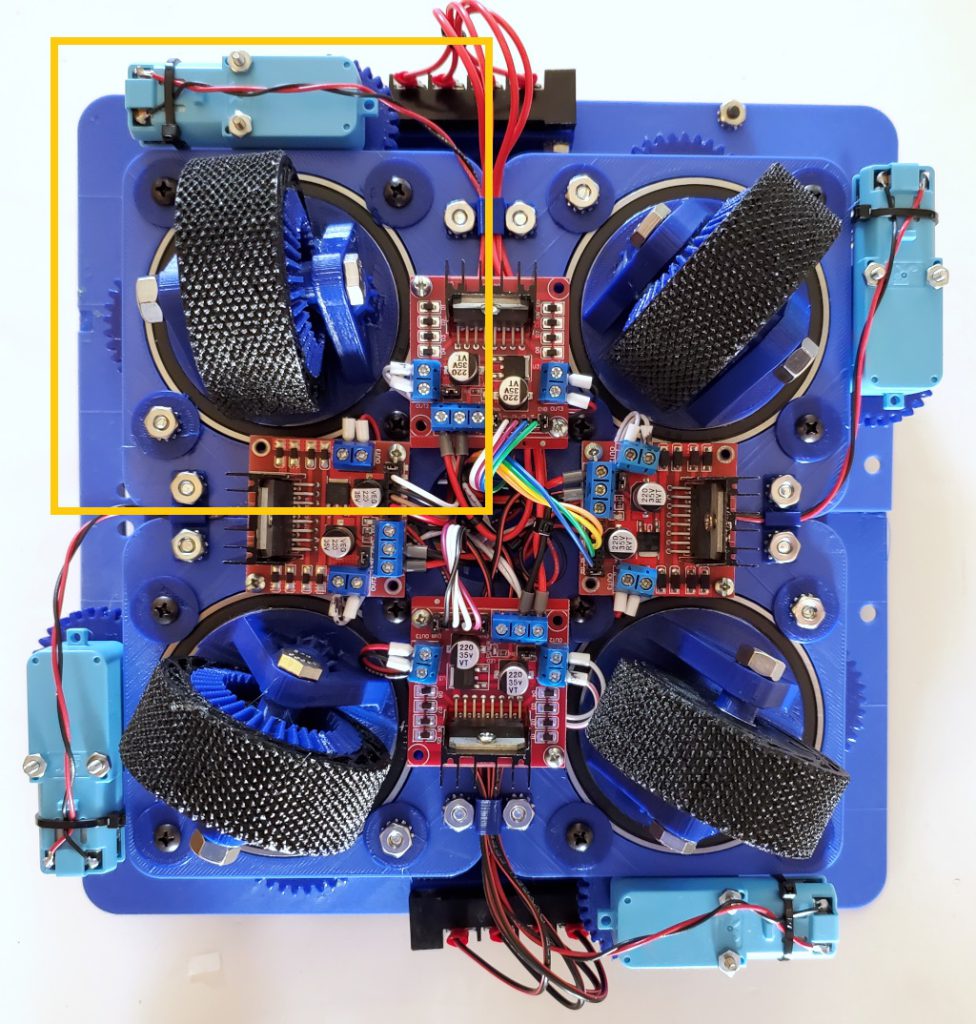
The yellow box in this image shows one of these modules. In particular this is the Swerve Module for the front left corner of the robot. If we view this module from a different angle we can see the two motors which control this wheel:
The motor marked Steering controls the orientation of the wheel. The wheel is free to rotate a full 360 degrees. The motor marked Drive powers the wheel and drives the robot.
SwerveModule class
Since we will have four of these modules for our robot, we need to create a class which we will call SwerveModule. Each instance of this class will control the two motors for that specific module. We will need to create four instances of this class, one for each corner of the robot. This class does not need to be defined as a subsystem, and should just be a simple class something like:
|
1 2 3 4 5 6 7 8 9 10 11 12 13 |
package frc.robot.subsystems; public class SwerveModule { private final PWMMotor m_driveMotor; private final PWMMotor m_steeringMotor; private final Encoder m_driveEncoder; private final Encoder m_steeringEncoder; public SwerveModule(int drivePWM, int driveDir, int driveEncInt, int driveEncDir, int steeringPWM, int steeringDir, int steeringEncA, int steeringEncB, int i2cAddr, String name) { } } |
Initializing motors
Since each Swerve Module will control two motors, we will need the pin numbers for each of the motors. To instantiate the motors you will need something like this:
|
1 2 |
m_driveMotor = new PWMMotor(drivePWM, driveDir, i2cAddr); m_steeringMotor = new PWMMotor(steeringPWM, steeringDir, i2cAddr); |
Note that we are using the constructor which includes the I2C address.
Initializing encoders
In addition, each motor has an associated encoder. For the Drive motor we use a relative Quadrature encoder. for the Steering motor we use an absolute AnalogRotational encoder. Hence we will also need the four pins the configure the two encoders. To instantiate the encoders you will need something like this:
|
1 2 3 |
m_steeringEncoder = new Encoder(robotCore.Encoder.EncoderType.AnalogRotational, steeringEncA, steeringEncB, i2cAddr, true); m_driveEncoder = new Encoder(robotCore.Encoder.EncoderType.Quadrature, driveEncInt, driveEncDir, i2cAddr, true); |
Once again note that we are using the constructor with the I2C address. Also note the last parameter group. If this is set to true then the read of the speed or position for the encoders are grouped at a low level to reduce the time needed to retrieve this information from the motors. In order to have sufficient bandwidth to operate the swerve drive it is important that group be set to true for these two encoders.
Finally, don’t forget to set the feedback device for the two motors:
|
1 2 |
m_driveMotor.setFeedbackDevice(m_driveEncoder); m_steeringMotor.setFeedbackDevice(m_steeringEncoder); |
DriveSubsystem
Finally, when you create the DriveSubsystem, you will need to create four instances of your SwerveModule class. You will, of course, need to know all of the required pin number and these are defined by the Swerve class:
Hence your DriveSubsystem class should look something like:
|
1 2 3 4 5 6 7 8 9 10 11 12 13 14 15 16 17 18 19 20 21 22 23 24 25 26 27 28 29 30 31 32 33 34 |
package frc.robot.subsystems; import edu.wpi.first.wpilibj2.command.SubsystemBase; import robotCore.Device; import robotCore.Logger; public class DriveSubsystem extends SubsystemBase { SwerveModule m_frontLeft = new SwerveModule(Swerve.FLDrivePWM, Swerve.FLDriveDir, Swerve.FLDriveEncInt, Swerve.FLDriveEncDir, Swerve.FLSteeringPWM, Swerve.FLSteeringDir, Swerve.FLSteeringEncA, Swerve.FLSteeringEncB, Swerve.FLI2CAddr, "FrontLeft"); SwerveModule m_backLeft = new SwerveModule(Swerve.BLDrivePWM, Swerve.BLDriveDir, Swerve.BLDriveEncInt, Swerve.BLDriveEncDir, Swerve.BLSteeringPWM, Swerve.BLSteeringDir, Swerve.BLSteeringEncA, Swerve.BLSteeringEncB, Swerve.BLI2CAddr, "BackLeft"); SwerveModule m_backRight = new SwerveModule(Swerve.BRDrivePWM, Swerve.BRDriveDir, Swerve.BRDriveEncInt, Swerve.BRDriveEncDir, Swerve.BRSteeringPWM, Swerve.BRSteeringDir, Swerve.BRSteeringEncA, Swerve.BRSteeringEncB, Swerve.BRI2CAddr, "BackRight"); SwerveModule m_frontRight = new SwerveModule(Swerve.FRDrivePWM, Swerve.FRDriveDir, Swerve.FRDriveEncInt, Swerve.FRDriveEncDir, Swerve.FRSteeringPWM, Swerve.FRSteeringDir, Swerve.FRSteeringEncA, Swerve.FRSteeringEncB, Swerve.FRI2CAddr, "FrontRight"); /** * Creates a new DriveSubsystem. */ public DriveSubsystem() { Logger.log("DriveSubsystem", 3, "DriveSubsystem()"); } @Override public void periodic() { // This method will be called once per scheduler run Logger.log("DriveSubsystem", -1, "periodic()"); } } |
In the next section we will tune the PID for the Steering motors.