The most interesting part of robot programming is the creation of autonomous actions where the robot performs a specific task without any human intervention. One important requirement for such autonomous routines is the ability of the robot to follow some precise path on the field.
To solve this problem we will be using a tool called PathPlanner which can be found here. This tool allows you to create these paths and hook them together along with other commands to create fully autonomous routines. In this chapter we will learn how to use this tool to create these paths and how to combine them with our own commands to get the robot to autonomously drive and shoot balls into a series of targets.
Double click on the pathplanner.exe file in the PathPlanner folder of utils and you should see:
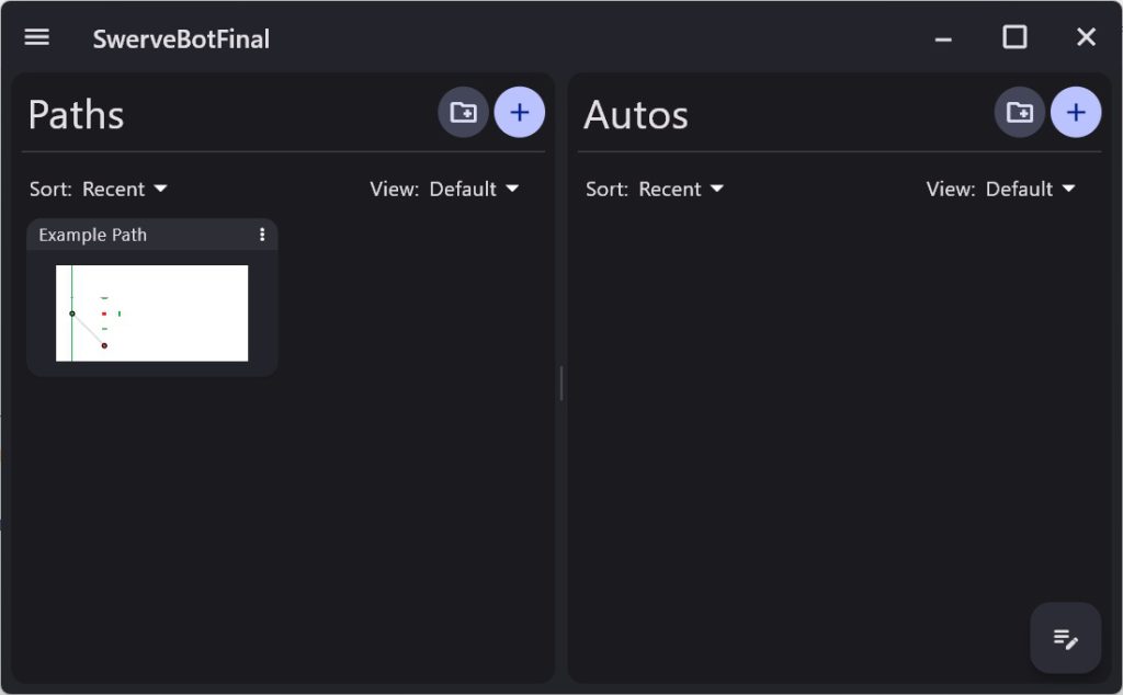
Here we have set up an example path on the left. Clicking on that will give you:
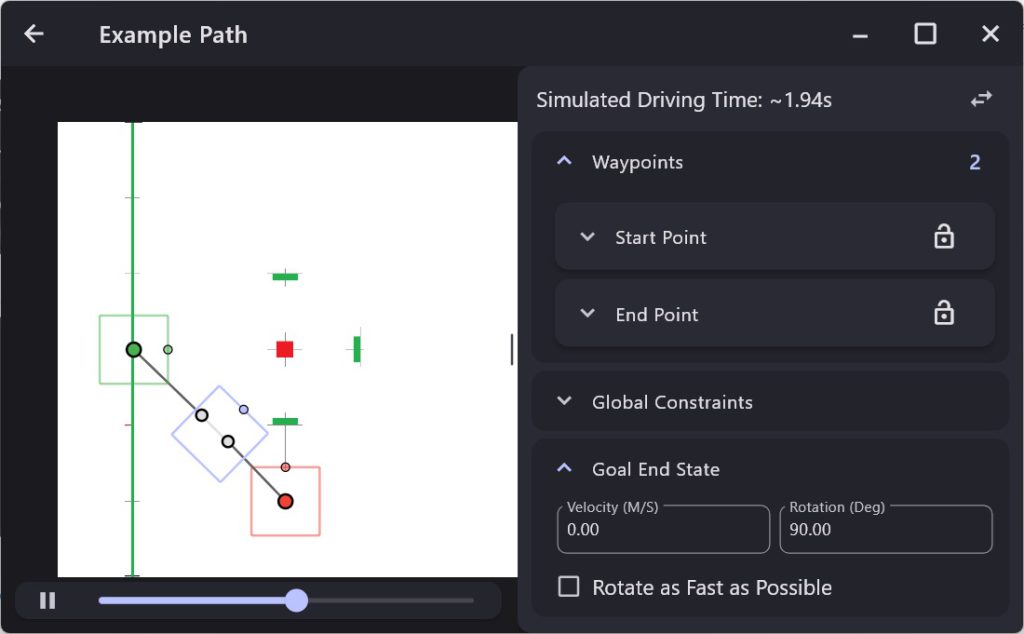
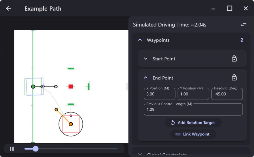
This display is actually animated and will show you the path of the robot. If you open the Start Point dropdown you can see the robot’s starting position for this path:
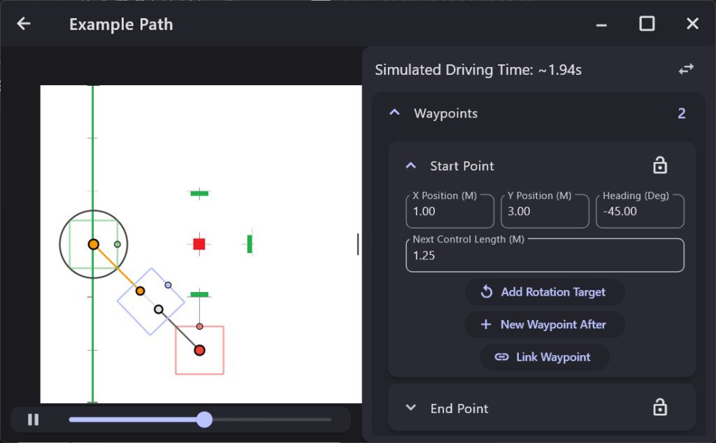
Here we can see that the robot starts at (x,y) = (1,3) (in meters) at a heading of -45 degrees. Note that the heading specifies the direction the robot will move, not the direction the robot is pointed. You can manually enter new numbers for the position and heading and you can also drag those points around. For example, I can drag the yellow line to that it is horizontal (i.e heading = 0 degrees) and the robot will move differently:
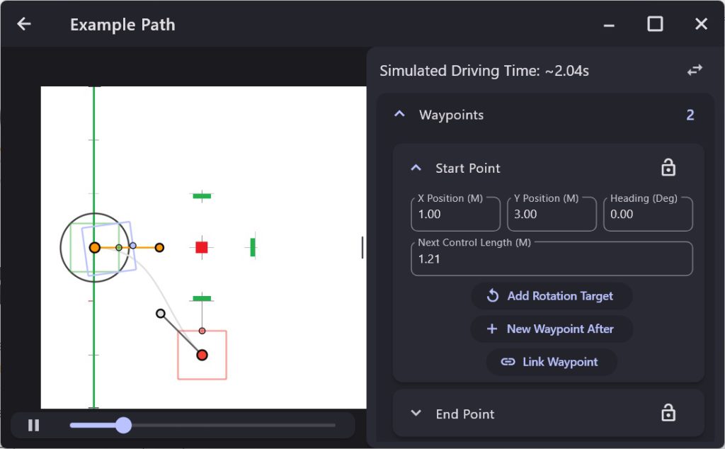
Notice how this change changes the path the robot will take. The grey line shows you the actual path.
The ending point can be edited in a similar manner by opening the End Point dropdown:
Autonomous Commands
Now that we have a path we need to create an autonomous path that we can command the robot to follow. From the main Pathplanner page, click the + button in the upper right corner:
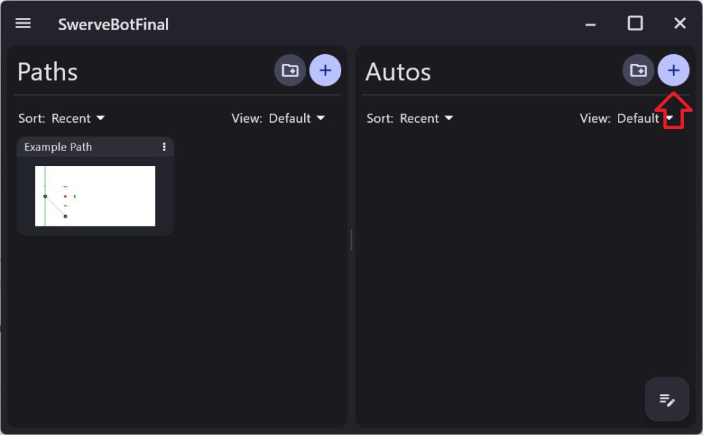
and you should see as New Auto created. Click in the name field and change the name to Auto1:

You can now click on Auto1 to edit it:
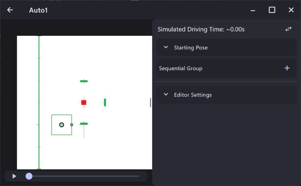
The first thing we must do is to set the Starting Pose so click on that dropdown:
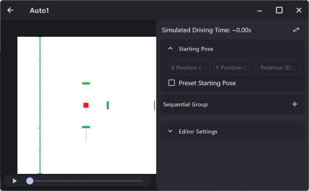
We will always be starting our robot within the view of one of the Apriltags and the robot’s position will be set from that so we don’t want the Pathplanner to set the initial Pose so be sure to uncheck the Preset Starting Pose checkbox.
Now we want to add our first command to run which will be the Example Path we were just looking at. Click on the “+” in the Sequential Group section:
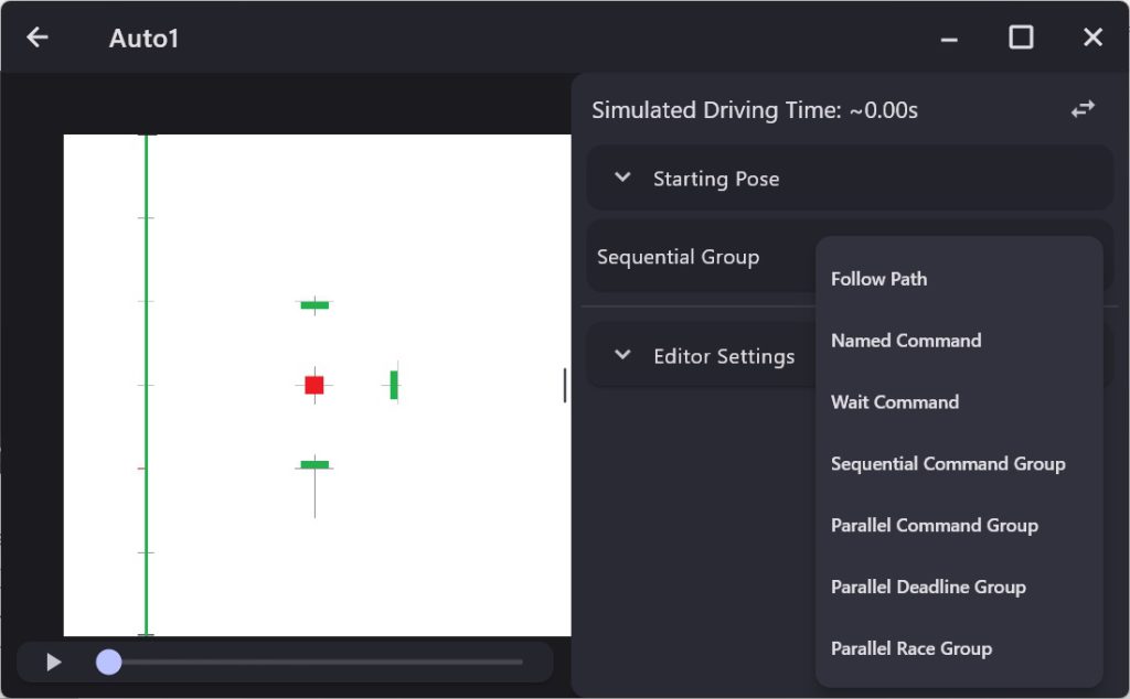
Then choose the Follow Path option:
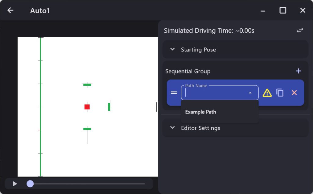
Then click on the Path Name option and choose the Example Path:
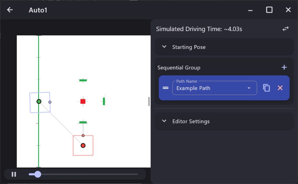
We can see that the robot will follow the Example Path that we created earlier.
Configure Pathplanner
Before we can create any commands we must first configure Pathplanner. We do this by adding a call to AutoBuilder.configureHolonomic in the constructor of our DriveSubsystem.
Looking at the documentation for this function we will need to supply seven pieces of information:
1) Robot’s position and orientation.
The first parameter of the configureHolonomic function is the position and orientation of the robot provided as a Pose2d structure. Let’s create a function to return this so we can get it whenever we need.
|
1 2 3 |
public Pose2d getPose2d() { return m_poseEstimator.getEstimatedPosition(); } |
Note that we are using the getEstimatedPosition function to obtain our best guess as to where the robot is.
2) Function that resets the robot’s pose (position and orientation) to a specified value.
Once again, we should create a function which will do this. Note that since we will be tracking the robot’s position using the Odometry and Apriltags, we will never actually let the Pathplanner set the robot’s position. Nonetheless we need to provide this function:
|
1 2 3 |
private void ResetPose(Pose2d pose) { m_poseEstimator.resetPosition(m_gyro.getRotation2d(), getModulePositions(), pose); } |
3) Robot’s relative chassis speed.
We need to compute and return the current relative chassis speed which we can do with the following function:
|
1 2 3 |
public ChassisSpeeds getChassisSpeeds() { return m_kinematics.toChassisSpeeds(getModuleStates()); } |
Note that we are using the wpilib function toChassisSpeeds to perform this calculation (which is fairly complex). This uses a function getModuleStates which returns the current state for each of the four modules. We can create this function as follows:
|
1 2 3 4 5 6 |
public SwerveModuleState[] getModuleStates() { SwerveModuleState[] states = { m_frontLeft.getState(), m_frontRight.getState(), m_backLeft.getState(), m_backRight.getState() }; return states; } |
Pay close attention the order of these states. They must match the order you used when you instantiated your SwerveDriveKinematics class.
4) Function which sets the chassis speed.
This function sets the current chassis speed and can be defined as follows:
|
1 2 3 |
public void setChassisSpeeds(ChassisSpeeds chassisSpeeds) { setModuleStates(m_kinematics.toSwerveModuleStates(chassisSpeeds)); } |
Once again this function will use a wpilib function toServeModuleStates which will compute the necessary state for each of the swerve module to get the robot to move as commanded. Note that this uses the setModuleStates function which we previously created.
5) Sets the HolonomicPathFollowerConfig.
This parameter configures the path following characteristics and can be created as:
|
1 2 3 4 5 6 7 |
new HolonomicPathFollowerConfig( new PIDConstants(1, 0, 0), new PIDConstants(1, 0, 0), k_maxDriveSpeedMetersPerSecond, (3.266 * 2.54) / 100, new ReplanningConfig(false, false)), |
This class contains a number of fields:
- PID values to be used for the robot’s translation (i.e. horizontal and vertical movement)
- PID values to be used for the robot’s rotation.
- The max speed of the individual swerve module wheels in meters/sec
- The Drive Base Radius which is the distance from the center of the robot to the furthest swerve wheel
- The ReplanningConfig which controls whether the path is automatically reconfigured at the beginning and ending of the path if the robot isn’t at the correct position. For our paths, we don’t want any reconfiguration.
6) Boolean supplier specifying whether the path needs to be flipped.
This is used for the 2024 FRC field but we will not be needing to flip the path so this parameter will always return false.
7) Subsystem
Specifies the subsystem that controls the swerve modules.
Now that we have defined all the functions we need, we can call the configureHolonomic function in the constructor of our DriveSubsystem:
|
1 2 3 4 5 6 7 8 9 10 11 12 |
AutoBuilder.configureHolonomic(this::getPose2d, this::ResetPose, this::getChassisSpeeds, this::setChassisSpeeds, new HolonomicPathFollowerConfig( new PIDConstants(1.5, 0, 0), new PIDConstants(3, 0, 0), k_maxDriveSpeedMetersPerSecond, k_driveBaseRadius, new ReplanningConfig(false, false)), () -> false, this); |
Creating an autonomous command
We are now ready to create our first autonomous command. We will create a command that will simply drive the path we create at the beginning of this chapter. We can define the new path command by adding the following to the constructor of the RobotContainer class.
|
1 |
m_auto1 = new PathPlannerAuto("Auto1"); |
Where we have defined m_auto1 as:
|
1 |
private final PathPlannerAuto m_auto1; |
Now attach the command to a button:
|
1 |
m_commandJoystick.button(11).onTrue(m_auto1); |
Set up the robot so that it starts 2 meters from the center Apriltag (i.e. tag #4), pointing directly at the tag. Then run the command and the robot should drive to the right of the center and rotate so that it is facing left.
Now when you run the command you may find that the robot does not actually reach the desired point and does not quite turn to the desired angle. This behavior can be improved by increasing the P terms for the Translation and Rotation PID controllers as follows:
|
1 2 3 4 5 6 7 8 9 10 11 12 |
AutoBuilder.configureHolonomic(this::getPose2d, this::ResetPose, this::getChassisSpeeds, this::setChassisSpeeds, new HolonomicPathFollowerConfig( new PIDConstants(2, 0, 0), // Change these lines new PIDConstants(2.5, 0, 0), // Change these lines k_maxDriveSpeedMetersPerSecond, (3.266 * 2.54) / 100, new ReplanningConfig(false, false)), () -> false, this); |
Note the changes made to the PIDConstants. By adjusting these numbers you can adjust how fast the robot responds to Translation and Rotation commands.
Adding other commands
Now we are going to want to do other things in our autonomous routines that just drive. For our autonomous routine, we are going to drive from the start position to a position that will allow us to shoot into target #1. So we want to add code that will automatically spin up the shooter and then shoot 10 balls when it reaches the target and finally stop when complete.
Now we have a SpinupCommand which we can use to spin-up the shooter wheel. Unfortunately this command never ends automatically (remember that we attached it to a button using toggleOnTrue) so we can’t simply run this command followed by the path command because this command will never end.
To get around this problem, we will need to run the SpinupCommand in parallel with the path command. To do this we will be using one of the Parallel Commands Groups that allows us to run commands in parallel. There are three such command available but we will choose ParallelRaceGroup. This type of command allow us to run commands in parallel and will end when the first command of the group ends.
In the Pathplanner Auto editor, click on the ‘+’ and add a new Parallel Race Group:
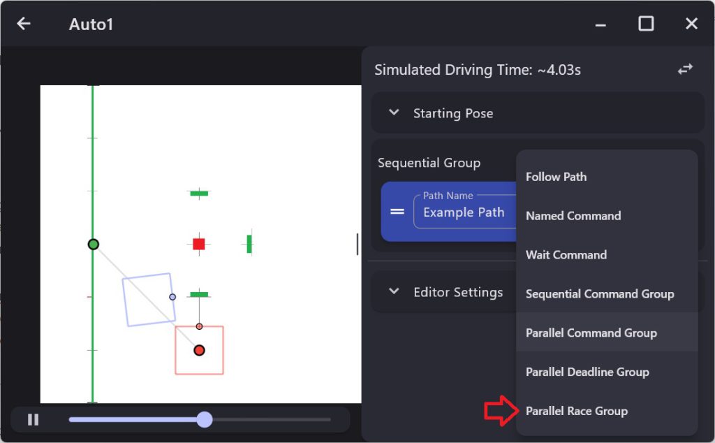
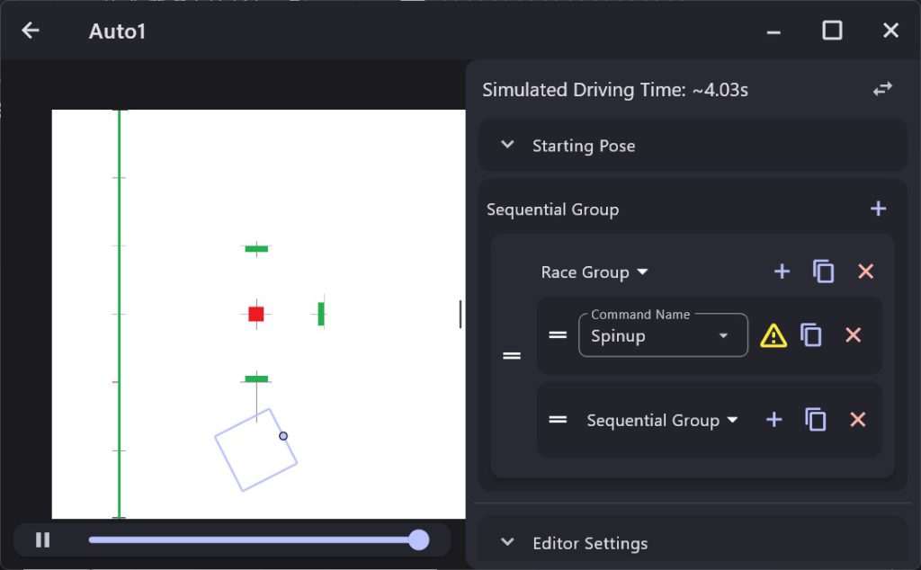
This will create a new ParallelRaceGroup command:
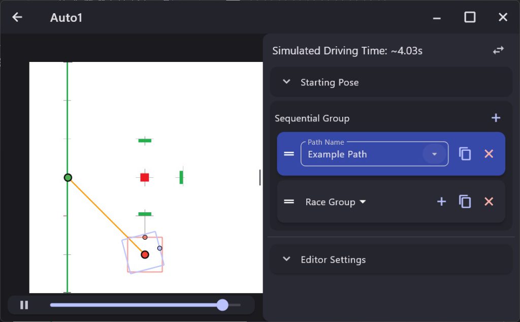
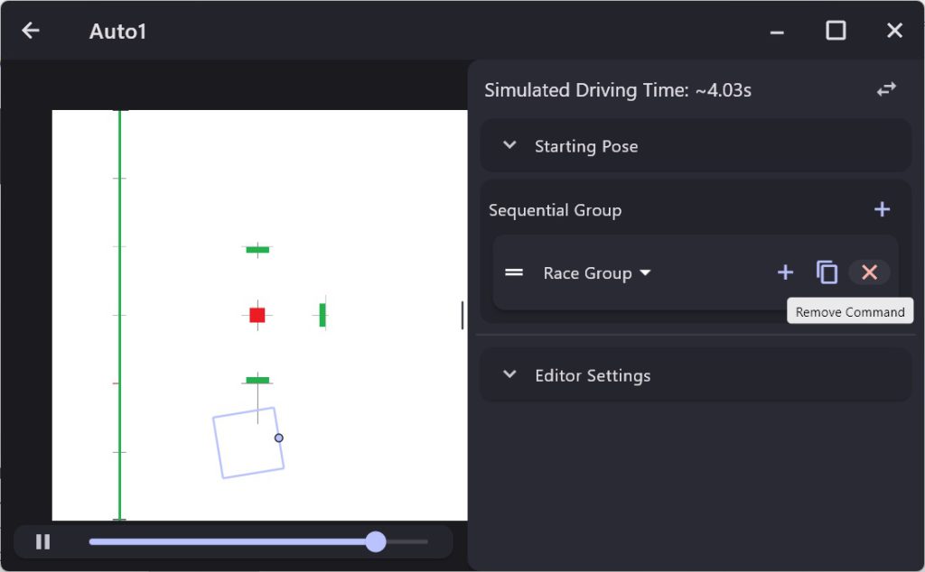
Now, it would really be nice if there was a way to move our Example Path into the Race Group, but, as far as I can tell there is not so we need to delete the Example Path by clicking on the ‘x’ next to it and add it back in later.
Now we need to add our SpinupCommand to the race group. Click on the ‘+’ button within the Race Group and choose Named Command and then enter the name Spinup in the Command Name box:
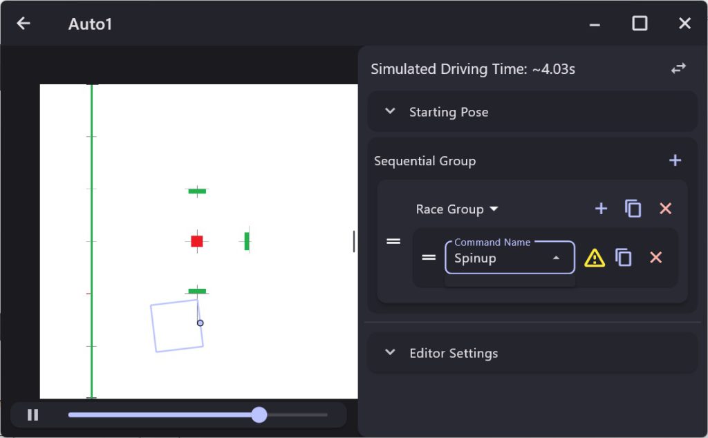
This will cause a command which we have named Spinup to run. We will need to add code to our project so that Pathplanner can find this command and we will do that later.
Now, in parallel with the SpinupCommand we are going to want to run two commands sequentially. The first is the Example Path command we created earlier which will move the robot to the shooting position, and the second is the FeederCommand which will actually shoot the balls.
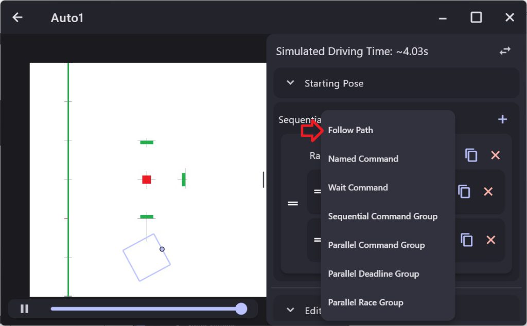
To make this happen, we need to create a SequentialCommandGroup within the Race Group. Once again click on the ‘+’ button within the Race Group and choose the Sequential Command Group option:
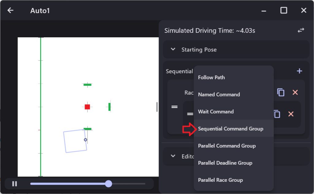
This should result in the following:
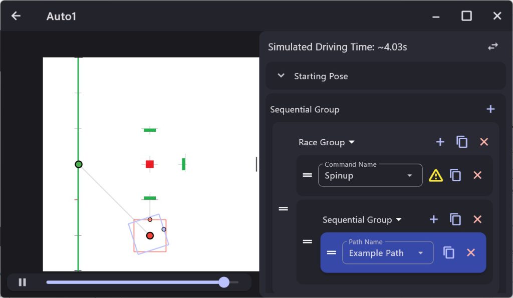
Now add the Example Path to the Sequential Group by clicking on the ‘+’ in that group and choosing the Follow Path option:
Then choose Example Path from the Path Name dropdown:
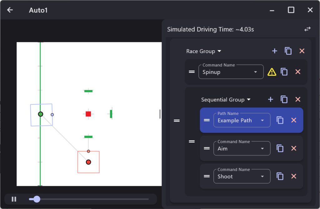
Now in the same Sequential Group add two Named Commands one called Aim and a second called Shoot:
We are now about ready to run our autonomous command but first we need to define the three Named Commands in our code. In the constructor for RobotContainer add the following lines:
|
1 2 3 4 5 |
NamedCommands.registerCommand("Shoot", new FeederCommand(m_feederSubsystem, true, 10)); NamedCommands.registerCommand("Aim", new TurnToTarget(m_driveSubsystem, 2)); NamedCommands.registerCommand("Spinup", new SpinupCommand(m_shooterSubsystem)); m_auto1 = new PathPlannerAuto("Auto1"); |
They should be added before you instantiate the auto path.
You are now ready to try out your new auto!