We are now ready to PID tune the drive motors.
Drive motor characteristics
The first thing you need to do is determine the drive motor characteristics. The two important number that we need are the minimum power and the max speed. Do get these we will once again create a command that will drive the robot forward using a power that ramps from 0 to about 1.2. The reason we go to 1.2 rather than the max of 1 is so that we can get a good measure of the maximum speed.
Create a new command TestDriveRamp. In the initialize function, set the steering position for all the motors to zero degrees so the robot will drive mostly straight. In the execute function log the power and the speed for all four of the drive motors. Then increment the power and set the new value. Then in the isFinished function return true when the power is greater than or equal to 1.2.
When I do this, this is my result:
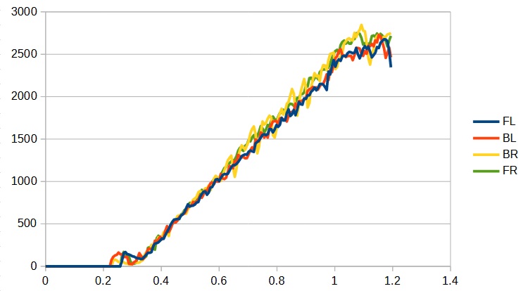
You need to glean two things from this graph. The first is the minimum power to get the motors to start. That value is the intersection of the linear portion of the graphs with the x axis. In this case you could estimate this from the graph to be about 0.3 for all of the motors. If you want a more precise answer, you can plot just the linear portions of the graphs and fit them to a line which will give you the intercept:
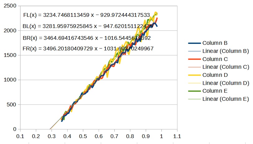
The second thing you need is the maximum speed. The max speed you set needs to be the slowest of the four motors. In my case it looks to be 2500. Define these values as constants in your DriveSubsystem and set call the setMinSpeed functions (which you must create) for the four module’s SwerveModule instance:
|
1 2 3 4 5 6 7 8 9 10 11 12 13 |
private static final double k_frontLeftMinDrivePower = 0.29; private static final double k_backLeftMinDrivePower = 0.29; private static final double k_backRightMinDrivePower = 0.30; private static final double k_frontRightMinDrivePower = 0.30; private static final double k_maxDriveSpeed = 2500; ... m_frontLeft.setDriveMinPower(k_frontLeftMinDrivePower); m_backLeft.setDriveMinPower(k_backLeftMinDrivePower); m_backRight.setDriveMinPower(k_backRightMinDrivePower); m_frontRight.setDriveMinPower(k_frontRightMinDrivePower); |
Now you are ready to tune the PID values. You should create a CalibrateDrive command. Like you do for the TestDriveRamp command, in it’s initialize function you should set the angle for all of the wheels to 0 degrees so the robot will drive straight:
|
1 2 3 4 |
m_frontLeft.setSteeringPosition(0); m_backLeft.setSteeringPosition(0); m_backRight.setSteeringPosition(0); m_frontRight.setSteeringPosition(0); |
IMPORTANT
Before we start, if you remember when we programmed the Minibot, we made a call to the setMaxSpeed() function of the PWMMotor class after we determined this value. We did this so we could use the output of the joystick (which had values between -1 and 1) as direct input to control the motor’s speed via the set() call. For the Minibot, this was a very convenient way to control the robot in our ArcadeDrive command.
However for this robot we will not be passing the joystick values directly to the motors. Instead we will call a complex function which will take the joystick values and compute the speed and angle for each of the swerve modules that will get the robot to drive in the correct direction. The speed that is returned from this function will be in meters/second and we will use these units to set the speed for the motors. As a result we do NOT want to call setMaxSpeed() for this robot. The setSpeed function that you create should always take the speed in the arbitrary encoder units. We will, of course, need to later create another function that will convert meters/second into these arbitrary units.
Now you can tune the F, P and I parameters (we generally don’t use the D parameter when tuning speed control). The method for doing this is similar to the one you used for the Minibot. First you set the F term (a good starting value would be 1.0/k_maxSpeed). You then add a P term and increase it until the speed becomes unstable. A good starting point for the P term would be 0.0001.
Finally you add the I term (along with an IZone) and increase that until the speed becomes unstable. A good starting point for the I term would be 0.0001.
When I tuned my robot the following were my results:
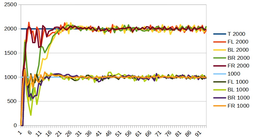
I did my tuning at a speed of 2000 and checked it at a speed of 1000. My final numbers were as follows:
|
1 2 3 4 5 6 7 8 9 |
private static final double k_frontLeftDriveF = 1.05 / k_maxDriveSpeed; private static final double k_backLeftDriveF = 1.05 / k_maxDriveSpeed; private static final double k_backRightDriveF = 0.95 / k_maxDriveSpeed; private static final double k_frontRightDriveF = 0.95 / k_maxDriveSpeed; public static final double k_drivePTerm = 0.0010; public static final double k_driveITerm = 0.0004; public static final double k_driveIZone = 200; |
Calibrate drive encoder
Finally we need to compute the conversion factor from encoder units (ticks, ticks/sec) to real world units (meters, meters/sec). To do this create a command CalibrateDistance. Set up this command to drive the robot forward at a relative slow speed for a short distance and record the position of each of the drive wheels using the encoder’s getPosition function.
I did this for my robot and found that 1.345 meters equals 3579 encoder ticks. This allows me to define the following constants in the DriveSubsystem:
|
1 2 3 |
private static final double k_maxDriveSpeed = 2500; private static final double k_ticksPerMeter = 3579 / 1.345; private static final double k_maxDriveSpeedMetersPerSecond = k_maxDriveSpeed / k_ticksPerMeter; // = 0.9395 m/s |
Which then allows me to create the following functions in the SwerveModule:
|
1 2 3 4 5 6 7 8 9 10 11 |
public void setDriveSpeedInMetersPerSecond(double speed) { setDriveSpeed(speed * DriveSubsystem.k_ticksPerMeter); } public double getDriveSpeedInMetersPerSecond() { return getDriveSpeed() / DriveSubsystem.k_ticksPerMeter; } public double getDrivePositionInMetersPerSecond() { return getDrivePosition() / DriveSubsystem.k_ticksPerMeter; } |
Remember, as discussed above, in order for this to work correctly your setDriveSpeed function must take the speed in the native encoder units of ticks/sec and not in the range of -1 to 1 which would be the case if you had used the setMaxSpeed() function as you did when programming the Minibot.