In this chapter we will configure and tune the four motors which orient the wheels. In the past we have used PID to control the speed of the motors but for the Steering motor we will be controlling the wheel’s position.
Motor measurements
The first thing we need to do is to run a test to measure some of the parameters of the motor. In particular we want to know what the minimum power that is needed to get the wheels to rotate. To do this you need to create a command that will ramp up the power for each of the wheels starting at zero and increasing to about 0.7 or so. If you don’t remember how to create a new command you can review that procedure from the Minibot tutorial here.
To create this command, you will need to add a function to your SwerveModule class that allows you to set the power for the Steering motor. Remember when you do this to be sure to set the motor mode to be sure it is in power mode:
|
1 2 3 4 |
public void setSteeringPower(double power) { m_steeringMotor.setControlMode(SmartMotorMode.Power); m_steeringMotor.set(power); } |
You will need to log the positions for each of the Steering motors so you should also add a function to your SwerveModule to get the current position. Note that this position will be in arbitrary units and not degrees. We will need to convert them to degrees later, but for now the arbitrary units will suffice:
|
1 2 3 |
public double getSteeringPosition() { return m_steeringEncoder.getPosition(); } |
Now the command will need access to all of the SwerveModule instances so you should create functions in your DriveSubsystem that will return those instances. For example:
|
1 2 3 |
public SwerveModuleGetFrontLeftModule() { return m_frontLeft; } |
When you do this, you need to log the position of the wheels to the console in a CSV format so you can plot it in Libre Calc. Note that when you do this, the wheels need to be under load. That is they should be in contact with the surface.
When you run your command you should verify that all of the wheels rotate in the counterclockwise direction when viewed from the top. If any of them rotate the wrong way you should call the setInverted function for that motor.
When I do this for my robot I get something like:
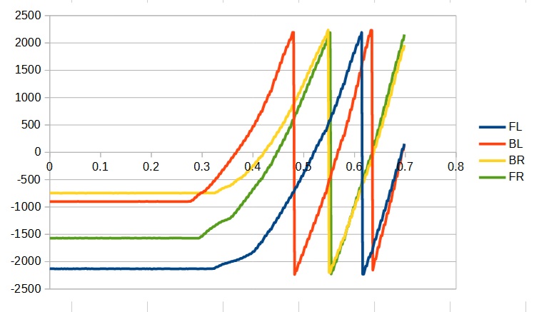
The first thing you need to check is that the position values increase over time. If any of the encoders decrease, you need to call the setInverted function for those encoders.
What you are looking for here is the power at which each of the wheels starts rotating. You can try and read this from the graph or you can look at the actual data. In my case I defined the following constants for each of the motors.
|
1 2 3 4 |
private static final double k_frontLeftMinSteeringPower = 0.33; private static final double k_backLeftMinSteeringPower = 0.28; private static final double k_backRightMinSteeringPower = 0.30; private static final double k_frontRightMinsteeringPower = 0.33; |
You then need to set the minimum power for each of the four Steering motors. To do this, create a function in the SwerveModule that allow you to set the value for that module:
|
1 2 3 |
public void setSteeringMinPower(double power) { m_steeringMotor.setMinPower(power); } |
and then set that from within your DriveSubsystem:
|
1 2 3 4 |
m_frontLeft.setSteeringMinPower(k_frontLeftMinSteeringPower); m_backLeft.setSteeringMinPower(k_backLeftMinSteeringPower); m_backRight.setSteeringMinPower(k_backRightMinSteeringPower); m_frontRight.setSteeringMinPower(k_frontRightMinsteeringPower); |
Setting the zero point
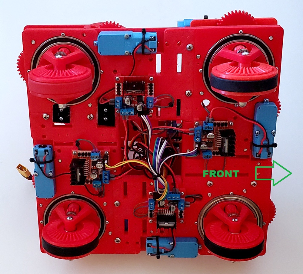
Next we need to set the zero point for all of the wheels. Align all of the wheels parallel to the right side of the robot with the gear side of the wheel facing right as shown below:
Now you need to have it print out the current Steering wheel positions for each of the wheels. You could create a command to do this, or you could simple print the values in the periodic function of the DriveSubsystem. Either way, here are the zero values I found for this robot.
|
1 2 3 4 |
private static final int k_frontLeftSteeringZero = 2565; private static final int k_backLeftSteeringZero = 3738; private static final int k_backRightSteeringZero = 2567; private static final int k_frontRightSteeringZero = 1452; |
Then create a setSteeringZero function in your SwerveModule class and call it four times in your DriveSubsystem to set the zero position for all of the wheels.
|
1 2 3 |
public void setSteeringZero(int zero) { m_steeringEncoder.setZero(zero); } |
Converting from Encoder units to degrees
Now create a function in your SwerveModule that will return the wheel’s position in degrees instead of the arbitrary units of the encoder. The Encoder function getRange will return the encoder value that represents 360 degrees so we can use it to convert the encoder value to degrees as in this new SwerveModule function:
|
1 2 3 |
public double getSteeringPositionInDegrees() { return Gyro.normalizeAngle(getSteeringPosition() * k_degreesPerTick); } |
Where we have defined k_degreesPerTick as:
|
1 |
k_degreesPerTick = 360.0 / m_steeringEncoder.getRange(); |
Note that we are using the utility function normalizeAngle provided by the Gyro class to force the resulting angle to be in the range of -180 to +180 degrees.
While it is useful to be able to get the encoder position in degrees, returned as a double, you will find that the Wpilib software often will require a Rotation2d class whenever an angle is needed. This class is more versatile than using straight degrees or radians since you can get the angle in whatever units you need. It is, therefore, useful to create a function that will return the encoder position in these units:
|
1 2 3 |
public Rotation2d getSteeringPositionRotation2d() { return Rotation2d.fromDegrees(getSteeringPositionInDegrees()); } |
Tuning the PID
We are now ready to tune the PID parameters to get the wheel to turn to any desired angle. Since this is Position PID tuning instead of Speed, we will only be using the P and D terms.
The first thing you need to do is to create functions in your SwerveModule that will let you set the P and D terms:
|
1 2 3 4 5 6 7 |
public void setSteeringPTerm(double p) { m_steeringMotor.setPTerm(p); } public void setSteeringDTerm(double d) { m_steeringMotor.setDTerm(d); } |
We also need a function that will set the position:
|
1 2 3 4 |
public void setSteeringPosition(double angleInDegrees) { m_steeringMotor.setControlMode(SmartMotorMode.Position); m_steeringMotor.set(angleInDegrees / k_degreesPerTick); // Convert to encoder units } |
Note that when setting the position, we need to convert the angle from degrees to encoder units.
You can try and tune all four motors at once, but I recommend that you work on one at a time. You should create a new command which sets the angle to a specific value and then create four instances of that command (tied to buttons) which will set the position to 0, 90, 180 and 270 degrees.
First start by setting the dead zone for all of the swerve modules. It is unlikely that you will need a different dead zone for each of the four modules so you can just set this in your SwerveModule constructor:
|
1 |
m_steeringMotor.setDeadZone(k_deadZone / k_degreesPerTick); |
A good initial choice for k_deadZone would be 2 degrees. Note also that for the call to setDeadZone we need to convert degrees into encoder units.
Now start by setting the P term. A good starting value might be:
|
1 2 3 4 |
private static final double k_frontLeftSteeringP = 1.0 / 360; private static final double k_backLeftSteeringP = 1.0 / 360; private static final double k_backRightSteeringP = 1.0 / 360; private static final double k_frontRightSteeringP = 1.0 / 360;; |
Note that we are defining a separate constant for each of the modules. This will allow us to use a different value for each.
Now run your program and test all 4 positions, 0, 90, 180 and 270. The goal is to have the largest P term that does not cause the wheel to oscillate. Once you find the right number it is time to add a D term to see if you can damp the oscillation. A good starting value for D might be:
|
1 2 3 4 |
private static final double k_frontLeftSteeringD = 0.005; private static final double k_backLeftSteeringD = 0.005; private static final double k_backRightSteeringD = 0.005; private static final double k_frontRightSteeringD = 0.005; |
You will find that when you add a D term, it will allow you to increase your P term without oscillating. The goal is to find the right combination of P and D terms that gets the wheel to the correct angle quickest without oscillation.
Repeat this process for all four wheels.